10
The control module SPTO 1D2 is able to
indicate the status of maximum 3 objects (cir-
cuit breakers or disconnectors) and to control
(open or close) one object.
The control module can be used for different
circuit breaker / disconnector / earth-switch
configurations within the above mentioned
limits. The configuration can be defined freely
by using configuration commands explained
below or by choosing a suitable default configu-
ration. Each default configuration uses a fixed
interlocking scheme.
The default configurations and interlockings
are explained in the appendixes 1…3. If the
configuration or the interlocking is not suitable
for a certain application then both must be
programmed by the user.
After factory testing the default configuration
and interlocking 1 has been selected for the
control module. Another default configuration
is chosen by writing the configuration number
for variable S100 via the SPA bus.
Normally the control module is in the run mode
which means that the interlocking program is
executed. When programming a configuration
or selecting a new default setting the control
module must be in the program mode (S198=0).
Example 1: Selection of the default configura-
tion and interlocking 2 instead of default 1.
>99WS198:0:XX
; Change into program mode
>99WS100:2:XX
; Select the default 2
>99WS198:1:XX
; Change into run mode
>99WV151:1:XX
; Store the programmed parameters
If variable S100 is 0, the configuration is freely
programmable. In this case all indicators are
initially set out of use. In a freely programmable
configuration, only the objects to be used must
be programmed.
The three input channels 1…3 can be used to
read status data of circuit breakers and dis-
connectors. The input channel numbers are
used when programming the feeder terminal
configuration.
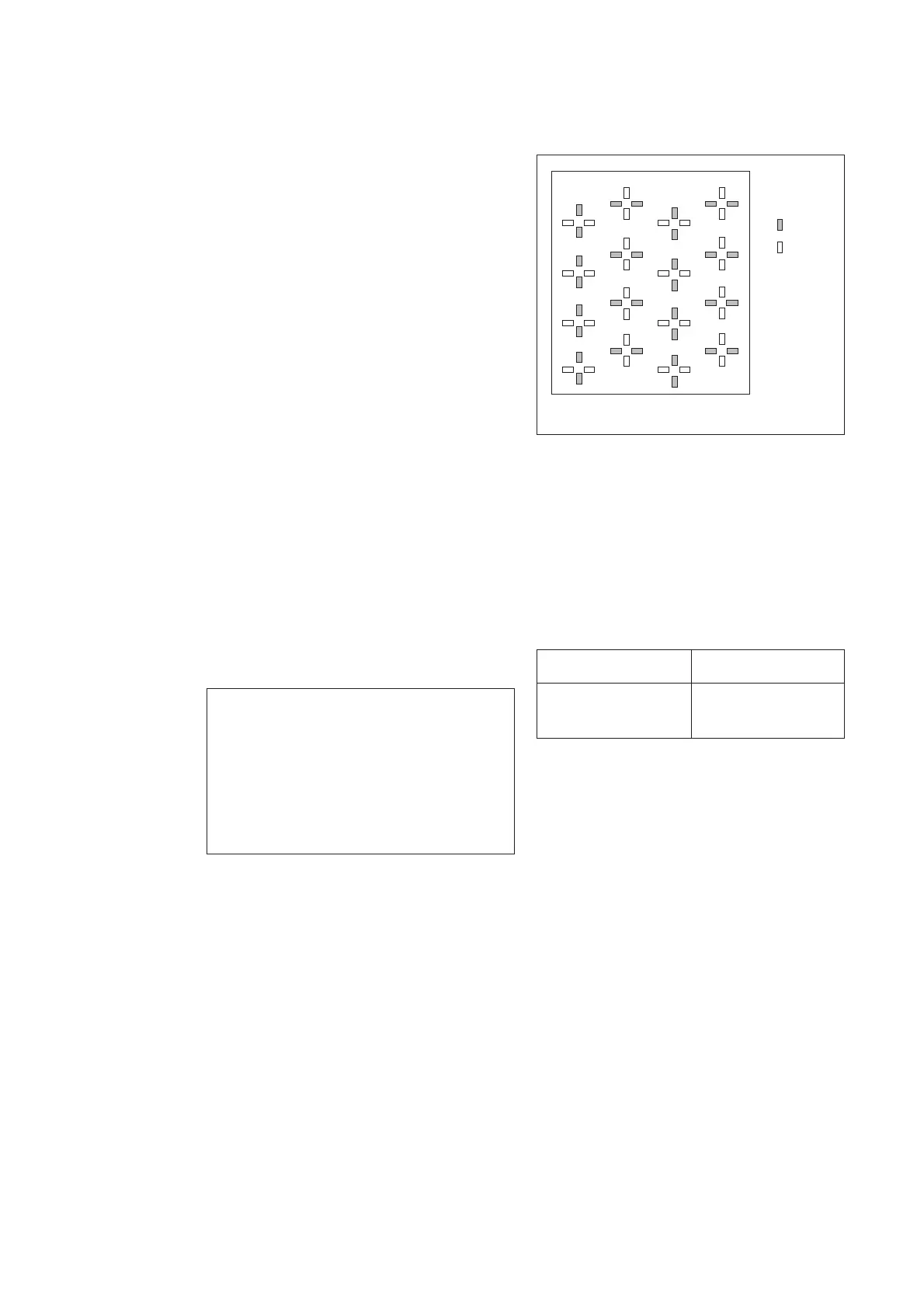
The front panel indicators are numbered from
101 to 116. These numbers are used when
programming the feeder terminal configura-
tion. The positions and the numbers of the
indicators in the matrix are shown in Fig. 6.
Fig. 6. Position, number and colour of the
indicators on the front panel of SPTO 1D2.
The control module has two outputs, OPEN
and CLOSE, for controlling one object. The
control outputs have their own codes, 20 and
21, which have to be used when programming
a configuration. The corresponding operation
is given in the following table.
Output code Operation
20 OPEN
21 CLOSE
For the correspondence between the input and
output codes and the rear panel terminal num-
bers see chapter "Connection diagram" in the
user´s manual of the feeder terminal.
When programming a configuration an indica-
tor number, a four-pole input number and an
output code are linked together using one SPA
protocol command.
The setting parameters S101…S116 which re-
fer to the indicator numbers 101…116 are
reserved for the configuration commands. As an
output number either the code of OPEN output
or CLOSE output can be used. Also some other
parameter, such as type of object and position of
open and closed status indicators, are defined in
the SPA protocol command.
Programming
Configuration
= red
= green
101
102
103
104
105
106
107
108
109
110
111
112
113
114
115
116
column column column column
1 2 3 4