6
Indicators for input
channels 4…9
The status of the input channels 4...9 is indi-
cated locally on the front panel. Channel 4 refers
to the upmost red indicator and channel 9 to the
lowest one.
An input can be defined to be active at high state
(NO contact) or active at low state (NC con-
tact). The LED is lit when the input is active.
The indication of the active status of the input
channels 4…9 can separately be programmed
to be memory controlled. If an input channel
indicator is memory controlled the LED indi-
cator remains lit until the channel is locally
reset by pressing the push-buttons STEP and
SELECT simultaneously or by remote control
via the serial interface using the parameter S5,
which is given the value 0 or 1.
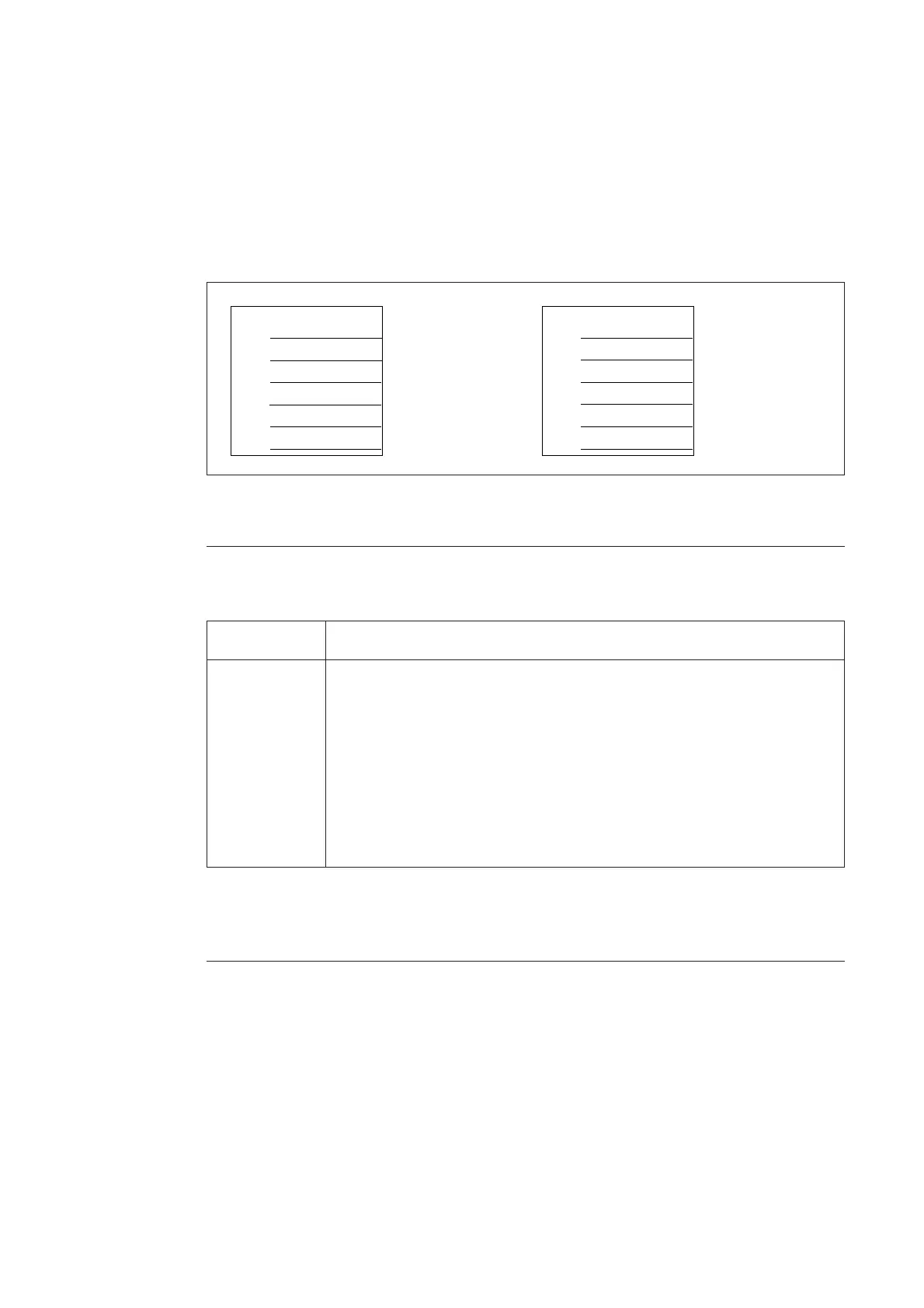
The front panel has a pocket for a text legend
foil, SYKU 997, on which the user can write the
desired input legend text. The left side of the
pocket is open. An empty text legend foil is
delivered with the relay package.
CB CONDITION
GAS PRESSURE
MOTOR VOLTAGE
CB CONDITION
GAS PRESS.
MOTOR VOLT.
Drawn with
1,8 mm
lettering guide
Drawn with
2,5 mm
lettering guide
Fig. 4. Example of text legend foil SYKU 997. The foil is shown in actual size, width 33.5 mm and
height 34 mm.
The control module includes two red operation
indicators showing the status of the module
itself. These LEDs are normally dark. The indi-
cators have the following function:
Operation indicators
Indicator Function
TEST Is lit when the switch SG1/1=1. Then the interlockings are out of use
INTERLOCK Is lit when a local control command is given and the operation of an object
is inhibited by the interlocking program. This LED can be switched off by
pressing the SELECT push-button or it is automatically switched off after
a timeout of about 30 seconds
When the control module is in the programming mode and the interlockings
are in use the indicator lights and it is switched off when the operation mode
is entered or when the interlockings are set out of use.
The green indicator U
aux
indicates that an exter-
nal power supply voltage is connected and the
power supply module of the unit is operating.
The input voltage range of the digital inputs and
the power supply module is marked below the
U
aux
indicator.
To be able to use the local OPEN and CLOSE
push-buttons, the key switch must be in the
position LOCAL, indicated by the yellow LED
L. All remote controls via the serial communica-
tion are inhibited, but control operations via
input channels 4…13 or control operations by
the conditional direct output control function
are allowed.
Accordingly, to be able to control an object via
the serial communication, the key switch must
be in the REMOTE position indicated by the
yellow LED R. When the key switch is in the
REMOTE position, local push-button controls
are inhibited.
The key can be removed both in local and in
remote position.
REMOTE/LOCAL
key switch