9
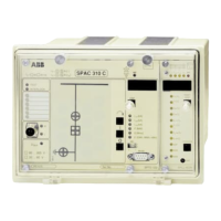
The 9-pin RS 232 interface on the front panel is
to be used for programming the control module
from a terminal or a PC. The control module
SPTO 1D2 supervises the serial communica-
tion of the feeder terminal. This enables protec-
tion modules of the same terminal to be set via
the RS 232 interface.
If a terminal or a PC is connected to the RS 232
interface the SPA-bus interface on the rear panel
of the feeder terminal is disconnected. When
using the RS 232 interface, the SPA-bus proto-
col has to be used.
The following serial communication param-
eters should be used:
- Number of data bits, 7
- Number of stop bits, 1
- Parity, even
- Baudrate, 9.6 kilobauds as a default
The next table shows the signal names and pin
numbers of the cable to be used between the RS
232 interface and a programming device.
RS 232 interface
RS 232 interface of SPTO 1D2 Programming device
Signal name Pin number Pin number Pin number Signal name
9-pin male conn. 9-pin female conn. 25-pin male conn.
Data receive 2 3 2 Data transmit
Data transmit 3 2 3 Data receive
Ground 5 5 7 Ground
DSR 6 4 20 DTR

 Loading...