13
Switchgroups
SGR1...9
The switchgroups SGR1...9 serve for con-
figuring the start and trip signals of the protec-
tion stages as desired output signals SS1...SS4
or TS1...TS4.
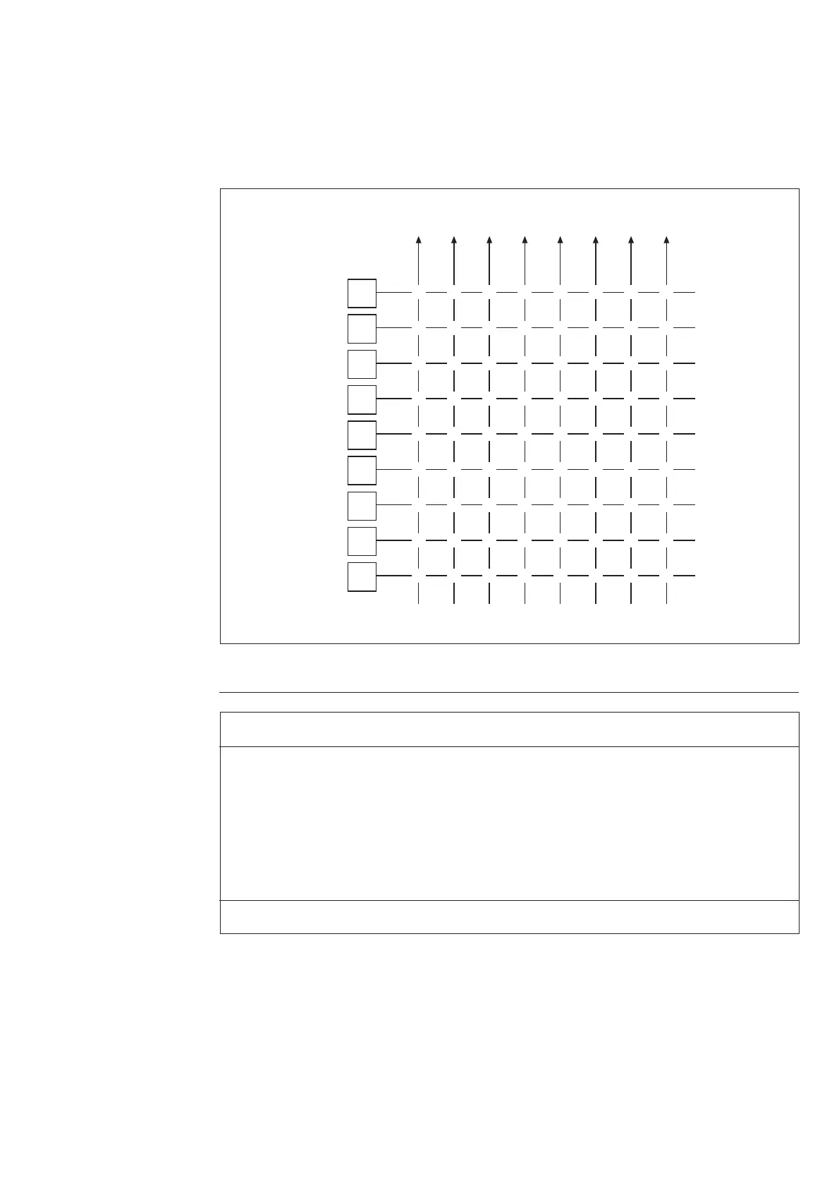
The matrix below can be used for the program-
ming. The start and trip signals are linked to
the desired output signal SS1...SS4 or TS1...
TS4, for example, by circling the intersection
of the signal lines. Each intersection is marked
with the number of the switch to be used and
the weighting factor of the switch is given un-
der the matrix. By adding the weighting factors
of the switches selected in each switchgroup, the
checksums shown to the right of the matrix are
received.
SGR1 t
1
t
1
'
t
2
t
2
'
t
3
t
3
'
t
4
t
4
'
1
1
1
1
1
1
1
2
3 4 5
2
2
2
2
2
2
3
3
3
3
3
4
4
4
4
4
4
8
6
5
5
5
5
5
16
6
6
6
6
6
32
7
64 128
8
78
78
78
78
78
Σ SGR1=
(Σ=2)
Σ SGR2=
(Σ=0)
Σ SGR3=
(Σ=1)
Σ SGR4=
(Σ=0)
Σ SGR5=
(Σ=8)
Σ SGR6=
(Σ=0)
1 2345678
Σ SGR7=
(Σ=8)
1 2345678
Σ SGR8=
(Σ=0)
1 2345678
Σ SGR9=
(Σ=0)
SS1 TS1 SS2 TS2 SS3 TS3 SS4 TS4
SGR2
SGR3
SGR4
SGR5
SGR6
SGR7
SGR8
SGR9
output signal
operation stage
switch-
group
recovery
function
Checksum
(Default setting)
weighting factor
Fig. 5. Output relay matrix for relay module SPCF 1D15.
Example of
checksum
calculation
Switch Weighting factor Position Value
SGF1/1 1 x 1 = 1
SGF1/2 2 x 0 = 0
SGF1/3 4 x 1 = 4
SGF1/4 8 x 0 = 0
SGF1/5 16 x 0 = 0
SGF1/6 32 x 0 = 0
SGF1/7 64 x 1 = 64
SGF1/8 128 x 0 = 0
Checksum ∑ of switchgroup SGF1 69