12
Switchgroups
SGB1...6
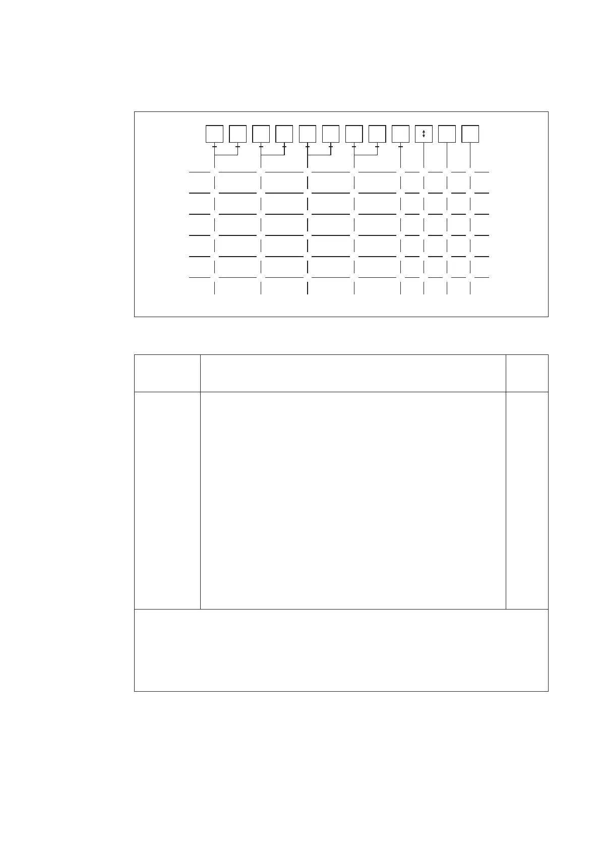
The switchgroups SGB1...6 are used for confi-
guring the control signals BS1…BS5. The ma-
trix below can be used for the programming.
The control signals and the desired functions
are linked to each other, for instance, by circling
the intersection of the lines. Each intersection
is marked with the number of the switch to be
used and the weighting factor of the switch is
given under the matrix. By adding the weight-
ing factors of the switches selected in each
switchgroup, the checksums shown to the right
of the matrix are received.
Fig. 4. Control signal matrix for relay module SPCF 1D15
Switch Function Factory
setting
SGB_/1...4 Blockings to be applied to the separate protection stages using
control signals BS1...BS6.
When a switch is in position 1, tripping by the concerned protection
stage will be blocked, when the control signal is activated.
SGB_/5 Blockings to be applied to the recovery stage using control signals
BS1...BS6
SGB_/6 Switching between main settings and second settings
If an external control input is used, the main setting values are active
when no control voltage is applied to the input, whereas the second
setting values are active, when the control input is energized.
SGB_/7 Resetting of front panel operation indicator
SGB_/8 Resetting of front panel operation indicator and registers
∑ SGB1 1
∑ SGB2 2
∑ SGB3 4
∑ SGB4 8
∑ SGB5 0
∑ SGB6 15
BS1
1
t
1
t
1
' t
2
t
2
' t
3
t
3
' t
4
t
4
'
BS2
1
BS3
1
BS4
1
BS5
1
1
1
2
3 4 5
2
2
2
2
2
2
3
3
3
3
3
4
4
4
4
4
4
8
6
5
5
5
5
5
16
6
6
6
6
6
32
7
64 128
8
78
78
78
78
78
Σ SGB1=
(Σ=1)
Σ SGB2=
(Σ=2)
Σ SGB3=
(Σ=4)
Σ SGB4=
(Σ=8)
Σ SGB5=
(Σ=0)
Σ SGB6=
(Σ=15)
undervoltage
blocking
weighting
value
Checksum
(Default setting)
main
second
indicators
indicators
registers
recovery
function