Setup and Installation
WBPEEUI240774A0 3 - 5
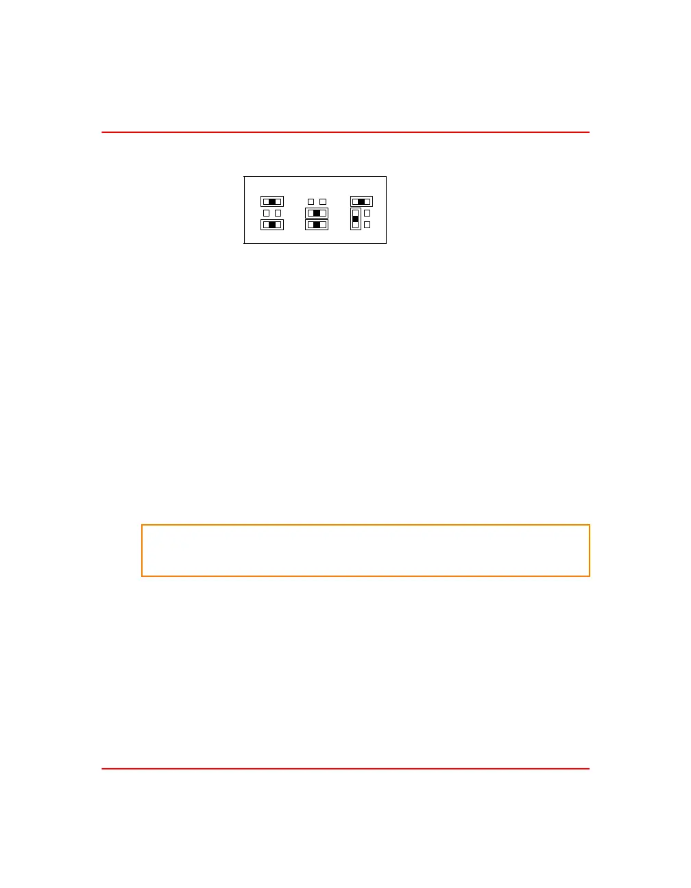
Refer to figure 3-3 for the jumper block configurations.
Termination Unit C onfiguration
An NTAI06 termination unit connects the field device wiring to
the Symphony system. The terminal blocks are located on the
termination unit. Set up the termination unit to accept the
analog field inputs sent to the IMASI23 module. Refer to
Appendix A for the termination unit information.
Physical Installation
NOTE: This section provides data on the physical installation of the analog
input module only. For complete cable and termination module information,
refer to Appendix A.
The IMASI23 module occupies one slot in a standard module
mounting unit (MMU). To install the module:
1. Verify the slot placement of the module.
2. Verify that a dipshunt is in the I/O expander bus socket on
the MMU backplane between the analog input module and
controller.
3. Connect the hooded end of the cable from the termination
unit to the MMU backplane. To do this, insert the connector
into the backplane slot in the same slot as the one assigned to
the analog input module. The latches should snap securely
into place.
Figure 3-3. Six Pin Jumper Block Configurations
mV/TC V/mA RTD
T04355A
WARNING
Disconnect power before installing dipshunts on the MMU
backplane. Failure to do so will result in contact with cabinet
areas that could cause severe or fatal shock.