Operation Manual / TPL69-A10 / -A30 ... TPL77-A10 / -A30
8 Disassembly and assembly / 8.8 Dismantling and fitting nozzle ring
at turbine end
© Copyright 2018 . All rights reserved. HZTL2481_EN Revision C May 2018
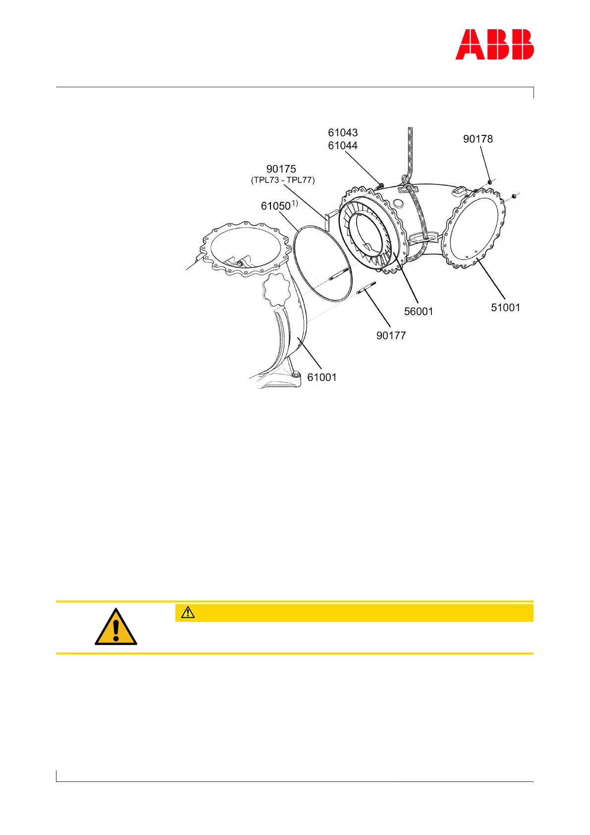
Flange connection disassembly
u Remove two hexagon-head screws (61044) together with Verbus
Ripp® washers (61043) from the bottom section and replace them
with two studs (90177).
u To secure, screw hexagon nuts (90178) onto studs (90177).
u Undo and remove the remaining screws (61044) and Verbus Ripp®
washers (61043).
TPL69
u Pull gas inlet casing (51001) together with nozzle ring (56001) away
from gas outlet casing (61001) until the nozzle ring can be lifted out.
TPL73 – TPL77
u Pull the gas inlet casing together with nozzle ring away from the gas
outlet casing until holder (90175) can be fitted from the outside using
screws (61044) and Verbus Ripp® washers (61043).
u Loosen the hexagon nuts (90178) on the studs.
u Fully withdraw the gas inlet casing and remove it.
CAUTION
When setting down the gas inlet casing to one side, use suitable under-
lays and take care not to damage the angles of the insulation.
1) If provided
u Remove spiral-wound gasket (61050).
TPL73 – TPL77
u Remove holder (90175) and then nozzle ring (56001).
Page 108 / 136