Operation Manual / TPL69-A10 / -A30 ... TPL77-A10 / -A30
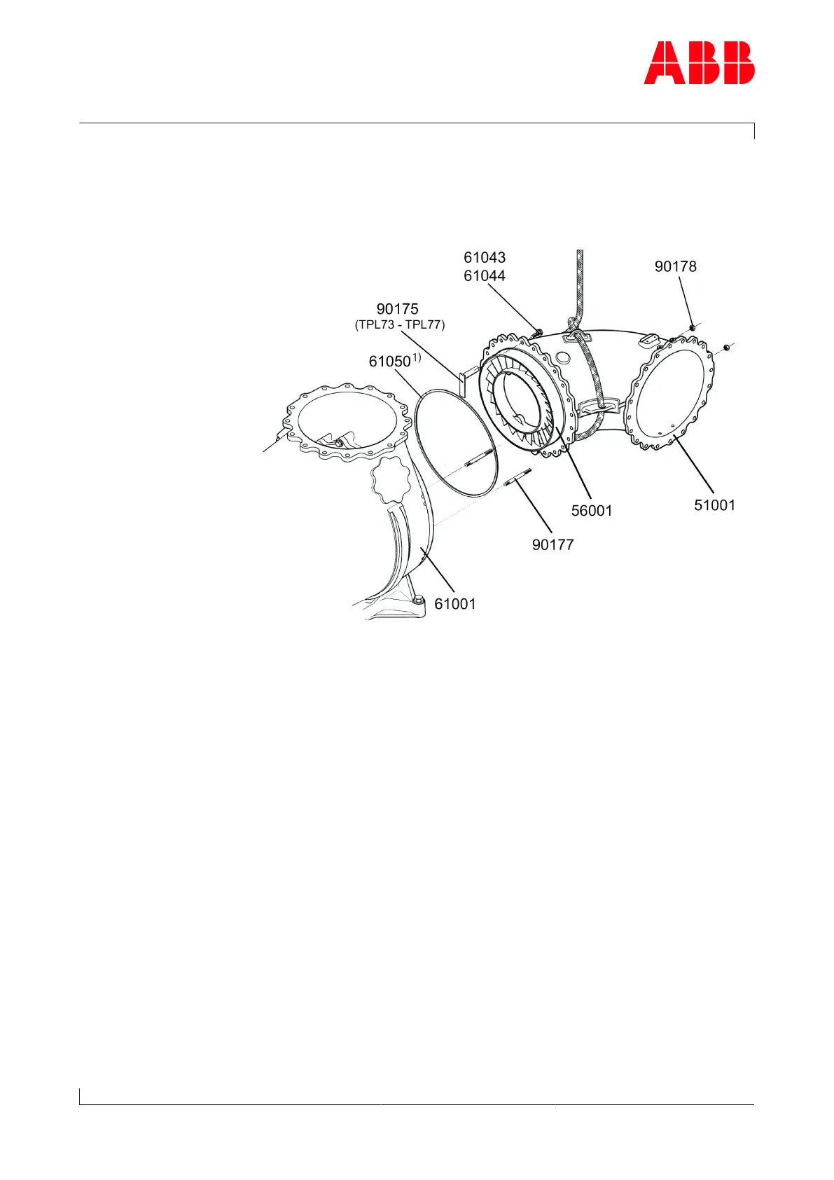
8 Disassembly and assembly / 8.8 Dismantling and fitting nozzle ring
at turbine end
© Copyright 2018 . All rights reserved. HZTL2481_EN Revision C May 2018
Flange connection assembly
u Carefully clean grooves and contact surfaces on the casing and keep
them free of metal chips.
u Keep grooves and spiral-wound gasket free from oil and grease.
1) If provided
u Fix a new spiral-wound gasket (61050) using a little instant adhesive
("Loctite® 454gel", for example) applied at three equally spaced
points in the groove.
TPL73 – TPL77
u Fit nozzle ring and place holder (90175) over the nozzle ring. Then
tighten holder (90175) using screw (61044) and Verbus Ripp® washer
(61043).
u Align gas inlet casing and secure using hexagon nuts (90178) on studs
(90177) .
TPL69
u Insert and position nozzle ring.
TPL73 – TPL77
u Remove holder (90175) and screw (61044) together with Verbus Ripp®
washers (61043).
u Coat thread of screws (61044) with high temperature grease.
u Fit gas inlet casing flange to gas outlet casing using finger-tight
screws (61044) and Verbus Ripp® washers (61043).
u Remove the hexagon nuts (90178) from the studs (90177).
u Replace the studs (90177) with hexagon-head screws (61044) and Ver-
bus Ripp® washers (61043).
Segment connection assembly
u Carefully clean slots and contact surfaces of the casings and keep
them free of metal chips.
Page 110 / 136