14 | XIO USER MANUAL | 2106424MNAB
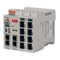
Figure 2-1: XIO housing cover
Legend: XIO housing cover
External power supply input (12 or 24 Vdc)
Cold button (paperclip actuated)
A Network Ethernet ports 1 and 2
B Network Ethernet ports 1 and 2
TFIO Module interface (male)
COM 1 – COM 8 Serial communication ports
(XIO-08 and XIO-04 only)
Reset button (paperclip actuated)
TFIO Module interface (female) (on the side)
Communication card status LEDs
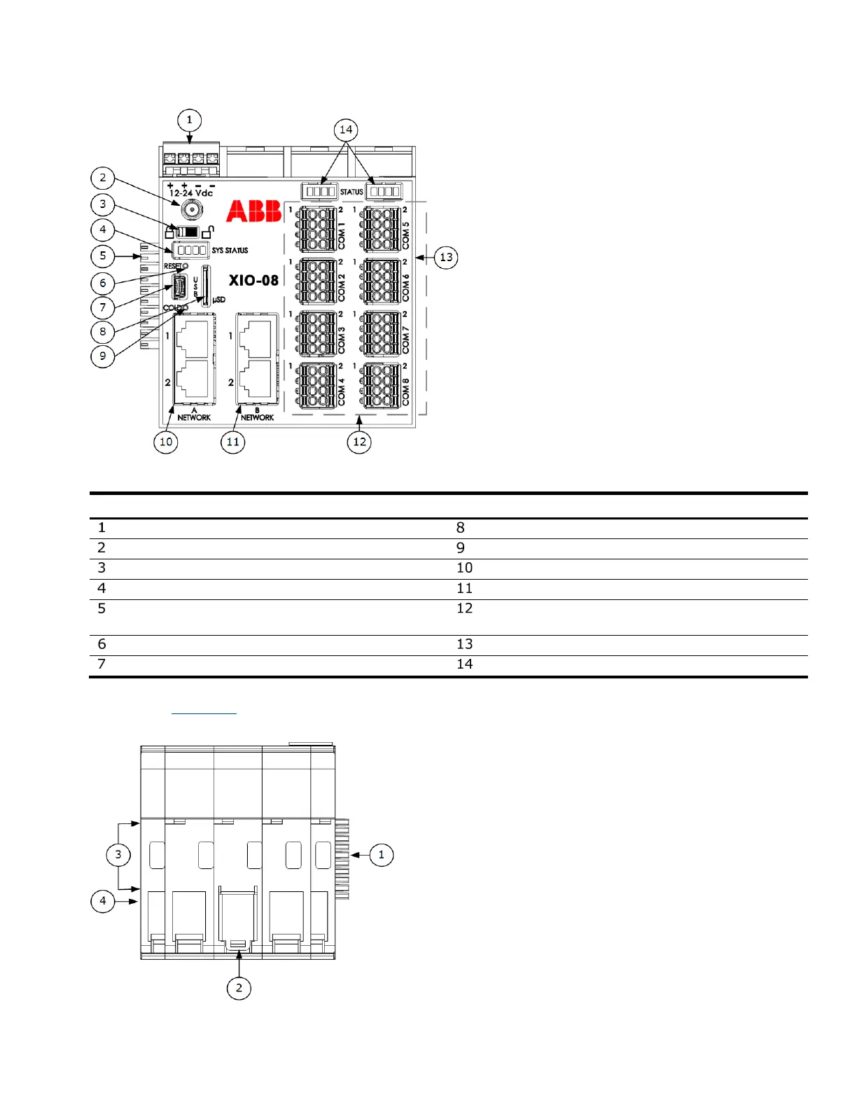
The electronic boards are inserted into a backplane at the base and the mounting clips are accessible on
the exterior. Figure 2-2
illustrates the exterior of the housing base.
Figure 2-2: XIO housing base
 Loading...