A-N68SV Series 5
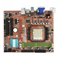
1.5.2 Front Panel Switches and Indicators Headers
This header is used for connecting switches and LED indicators on the
chassis front panel.
Watch the power LED pin position and orientation. The mark “+” align
to the pin in the figure below stands for positive polarity for the LED
connection. Please pay attention when connecting these headers. A
wrong orientation will only result in the LED not lighting, but a wrong
connection of the switches could cause system malfunction.
• HLED (Pin 1, 3):
Connects to the HDD LED cable of chassis front panel.
• RST (Pin 5, 7):
Connects to the Reset Switch cable of chassis front panel.
• SPKR (Pin 13, 15, 17, 19):
Connects to the System Speaker cable of chassis.
• SLED (Pin 2, 4):
Connects to the Suspend LED cable (if there is one) of chassis
front panel.
• PWR (Pin 6, 8):
Connects to the Power Switch cable of chassis front panel.
• PLED (Pin 16, 18, 20):
Connects to the Power LED cable of chassis front panel.
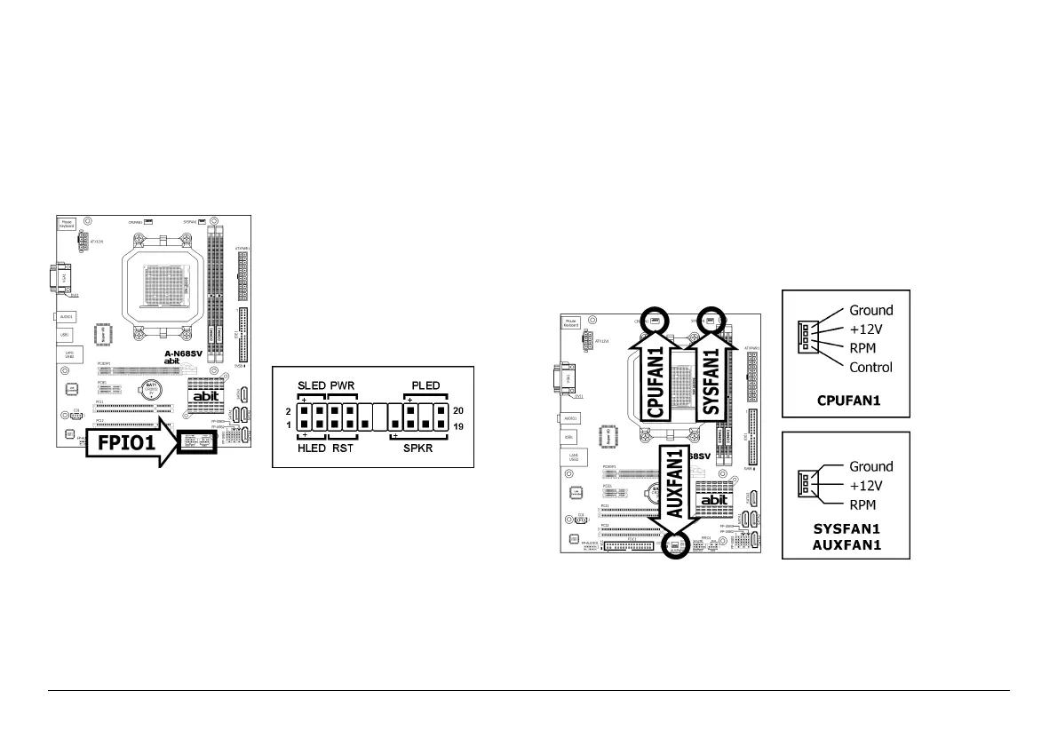
1.5.3 FAN Power Connectors
These connectors each provide power to the cooling fans installed in
your system.
• CPUFAN1: CPU Fan Power Connector
• SYSFAN1: System Fan Power Connector
• AUXFAN1: Auxiliary Fan Power Connector
※
These fan connectors are not jumpers. DO NOT place jumper caps
on these connectors.
 Loading...