Hardware Setup
AN-M2/AN-M2HD 1-9
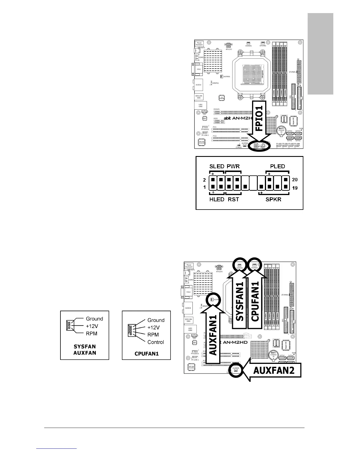
1.6.2 Front Panel Switches & Indicators Headers
This header is used for connecting switches and
LED indicators on the chassis front panel.
Watch the power LED pin position and orientation.
The mark “+” align to the pin in the figure below
stands for positive polarity for the LED connection.
Please pay attention when connecting these
headers. A wrong orientation will only result in the
LED not lighting, but a wrong connection of the
switches could cause system malfunction.
• HLED (Pin 1, 3):
Connects to the HDD LED cable of chassis
front panel.
• RST (Pin 5, 7):
Connects to the Reset Switch cable of chassis
front panel.
• SPKR (Pin 13, 15, 17, 19):
Connects to the System Speaker cable of
chassis.
• SLED (Pin 2, 4):
Connects to the Suspend LED cable (if there
is one) of chassis front panel.
• PWR (Pin 6, 8):
Connects to the Power Switch cable of
chassis front panel.
• PLED (Pin 16, 18, 20):
Connects to the Power LED cable of chassis front panel.
1.6.3 FAN Power Connectors
These connectors each provide power to the
cooling fans installed in your system.
• CPUFAN1: CPU Fan Power Connector
• SYSFAN1: System Fan Power Connector
• AUXFAN1~2: Auxiliary Fan Power
Connector
※ These fan connectors are not jumpers. DO NOT place jumper caps on these
connectors.