Installation & Operation Manual - Model AVC5000
Contents of this Manual are Subject to Change Without Notification Page 42
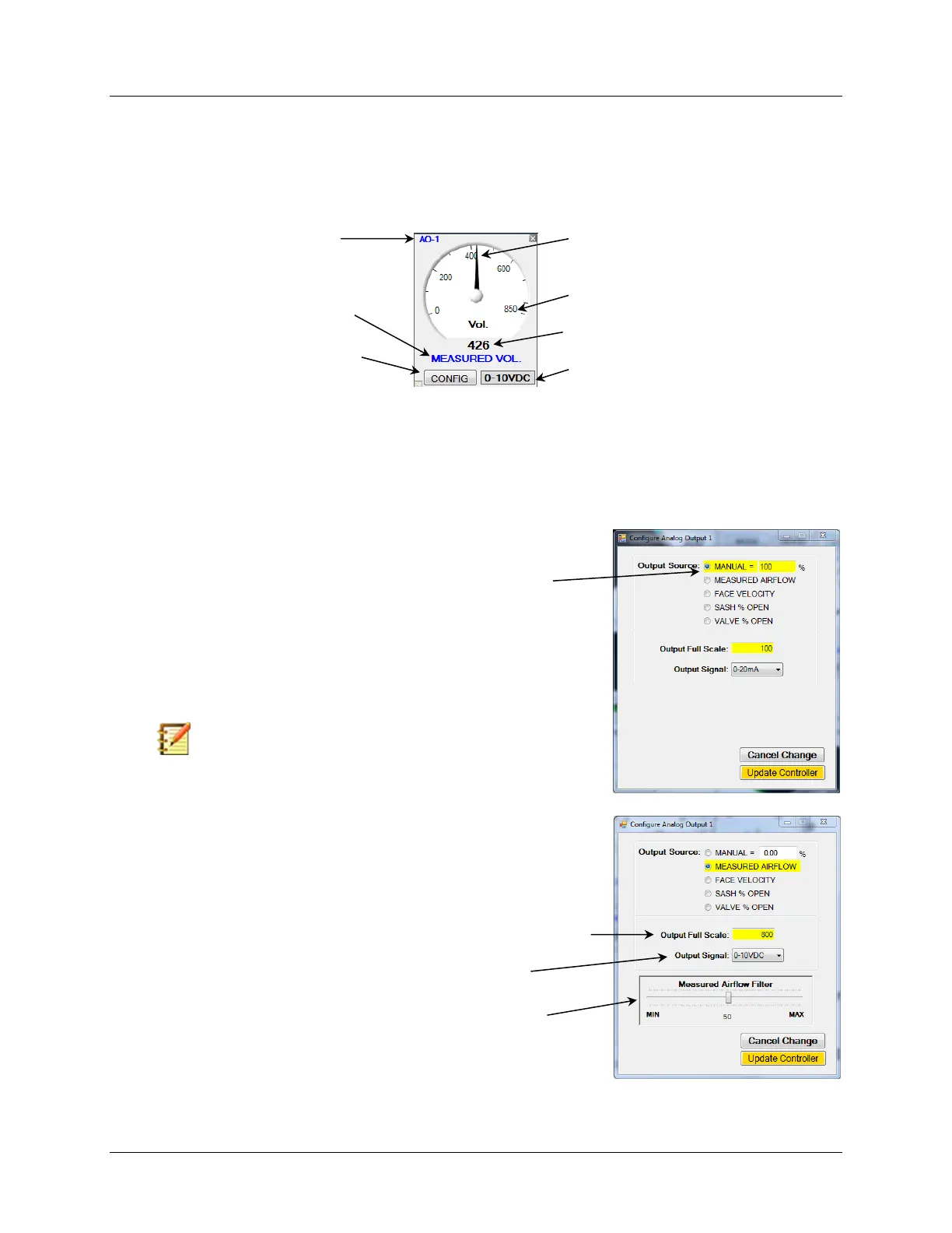
6.6.5 Analog Output Gauges
There are two Analog Output Gauges, AO-1 and AO-2, provided for indicating the status and
configuration of each Analog Output. Both of the Analog Output Gauges operate in a similar
manor and each can be configured independently. Access to the Analog Output Configuration
Menu is provided by selecting the “CONFIG” button.
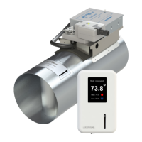
6.6.5.1 Analog Output Configuration
Selecting the “CONFIG” button on the one of the Analog Output Gauges will open a window
that will enable you to enter all the configuration parameters available for that Analog Output.
The examples provided below explain the parameters available and how to configure each.
Select “CONFIG” to Open
Configuration Window
Present Analog Output Configuration
Analog Output
Corresponding to Gauge
Selecting Output Source to “MANUAL” sets the Analog Output to a fixed
value corresponding with the value entered after the “=”.
For example; If the Output Source is configured to “MANUAL = 100%”
with Output Full Scale set for “100”and the Output Signal set for 0-
20mA, then the Analog Output will continuously read 20mA.
Changing the Output Source to “MANUAL = 50%” will result in the
Analog Output continuously reading 10mA.
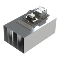
Selecting “MEASURED AIRFLOW” sets the Analog Output to correspond
with the Airflow Volume.
The Output Full Scale provides the FS range for the Gauge and Analog
Output Signal. This example is set for 800 CFM.
Filtering can be applied to the output value by using the slider.
The Output Signal Type is selected from the dropdown list.
Note: This can be a useful feature for troubleshooting.