Installation & Operation Manual - Model AVC5000
Contents of this Manual are Subject to Change Without Notification Page 44
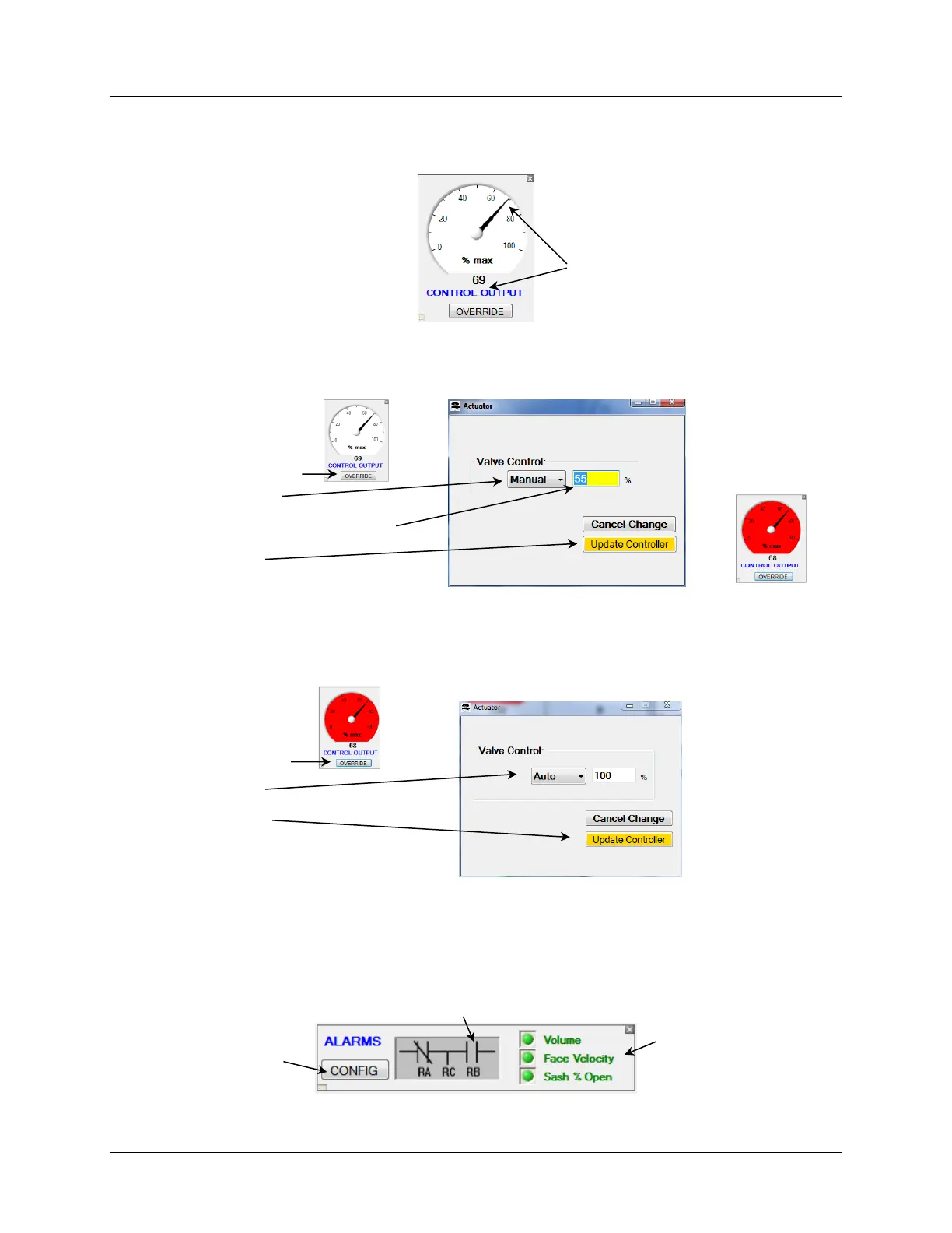
6.6.6 Control Output Gauge
The Control Output Gauge displays the Control Output % and also provides a means for
overriding the control-loop output enabling direct command of the actuator.
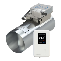
6.6.6.1 Control Output Override
Sometimes it is necessary to temporarily override the control loop and set the control output to
a constant value.
NOTE: With “OVERRIDE” activated the Gauge Face color changes to Red.
Because the Override function is not intended to be used for extended durations the manual
override value is not saved to the controller’s nonvolatile memory. A power cycle will release
the control to Auto.
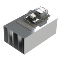
6.6.7 Alarm Indicator Diagram
The Alarm Indicator Diagram provides a visual indication of the alarm status, real-time
monitoring and visual status of the alarm relay state and a Configuration Button to access the
Alarm Configuration Screen.
Green = Alarm Enabled, Normal
Red = Alarm Enabled, ALARM
Gray = Alarm Disabled