5 | Page
2.2 Choosing a Location
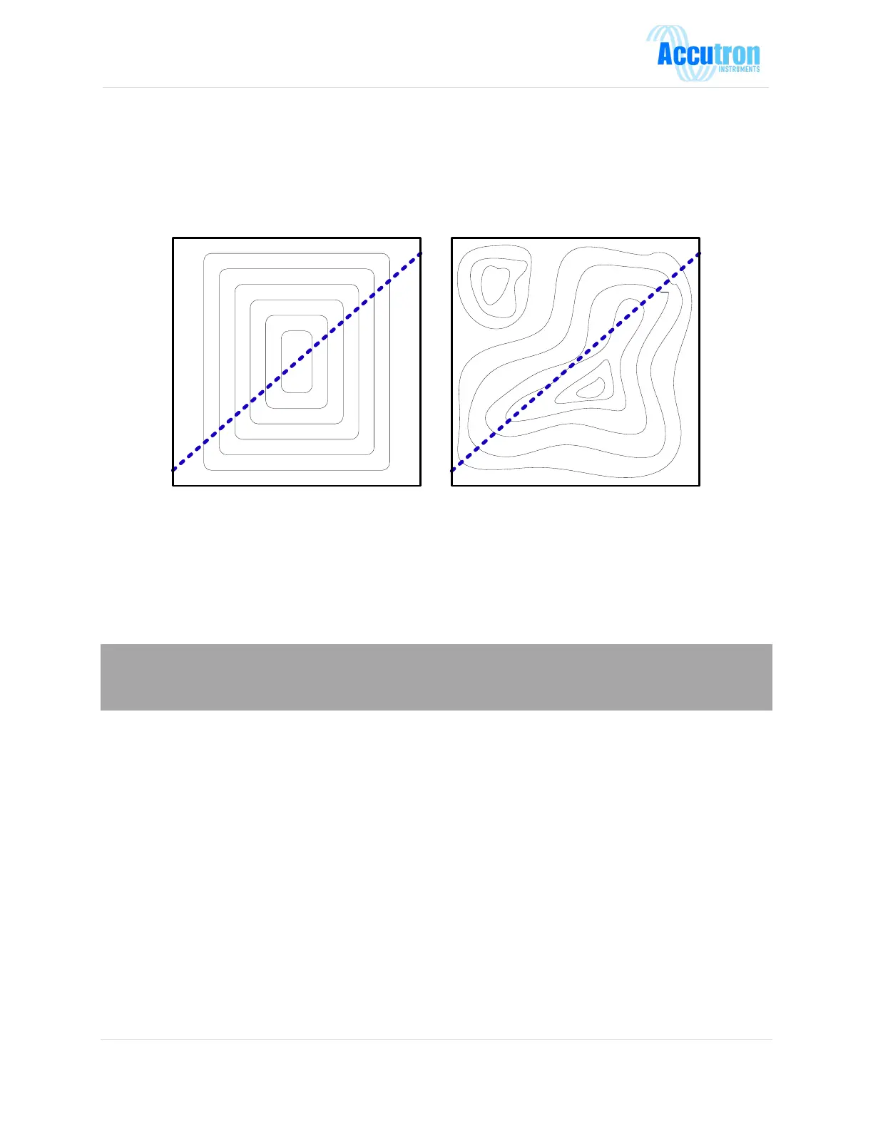
The best location to install the instrument is in a straight section of tunnel that is at least 3 tunnel widths
long. In such a section, the airflow distribution will be well behaved with a maximum airflow in the
center and minimum airflow on the sides (Figure A). We should try to avoid locations where the airflow
is concentrated in one of the corners (Figure B).
The imaginary line between the Accutron sensors works like a “virtual pitot tube” and all flow
measurements occur along this line. In practice, best results are produced when this “imaginary line”
passes through the center of the tunnel, slicing through the airflow distribution profile in a
representative way.
It is also a good idea to carry out and record a 9-point manual airflow survey to verify the airflow
distribution and identify it as a suitable location.
Note: If we need to measure airflow in a less-ideal location. We may need to manually adjust the
calibration correction factor to give accurate flow readings. In this case, the instrument would be
calibrated against a handheld anemometer.
2.3 Mounting the Display
When planning to mount the control unit, you must take into consideration the availability of the power
source, the 4-20mA output signal (i.e., PLC connection), and the sensor cable lengths. In most cases the
control box is mounted on the wall in an electrical room. Extended sensor cable lengths are available for
distances greater than 100 feet.