1-12 User’s Guide
4. Insert the upgrade CPU (with the heatsink) into the upgrade
socket. Make sure that pin 1 of the CPU corresponds to hole 1 of
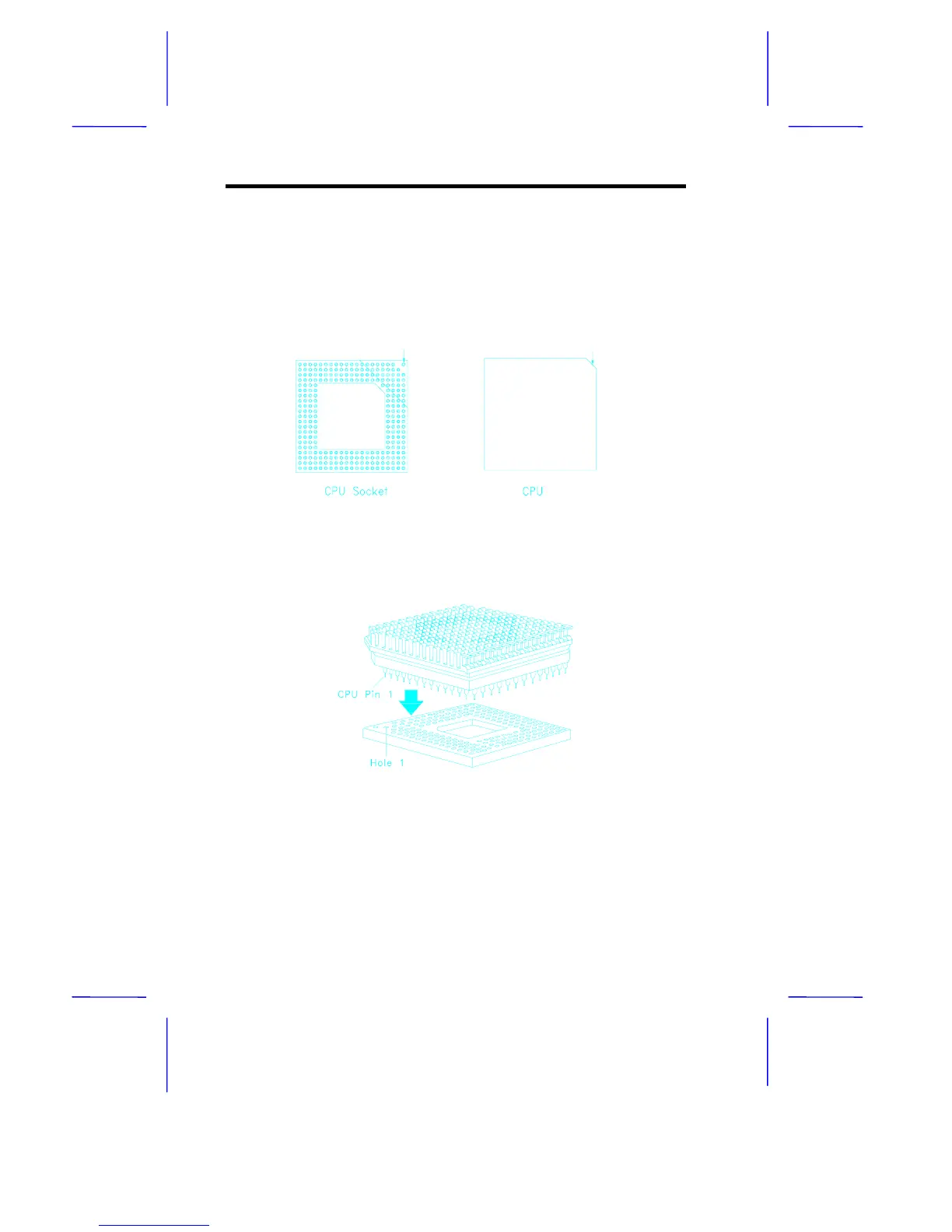
the upgrade socket (see Figure 1-6). The flat corner on the CPU
indicates pin 1. Insert the CPU pins into the socket pinholes
gently but firmly. Be careful not to bend any pins.
Figure 1-5 Pin 1 Indicator on the Upgrade CPUand Socket
Figure 1-6 Installing an Upgrade CPU
5. Set the required jumpers on the system board. Refer to section
1.4 for the jumper settings.
Pin 1 Indicator
Pin 1 Indicator
(flat corner)