System Housing 1-21
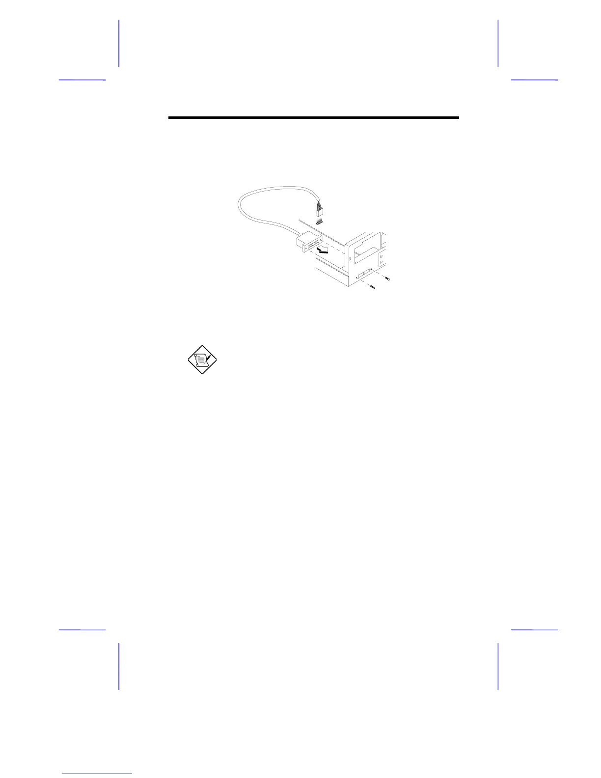
4. Attached the USB connector cable to the system board. Using a
screw driver, secure the connector to the housing’s opening at the
back. The USB connector opening is located on the lower-left side
of the housing (at the back).
Figure 1-22 Attaching the USB Connector Cable to the System
Board
For more information about the system
board’s connectors, please refer to the
system board’s manual.
5. Secure the Front I/O Board (located in front of the housing) with
the appropriate screw as shown below.