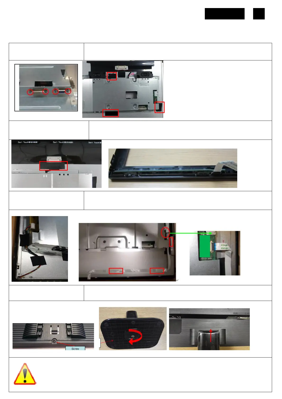
Lock the Hexagonal screws as picture 1.
Use jig to put the SHD in correct position on Panel. Take off the jig and stick 3 acetic
tapes as picture 2.
S4
Assemble LVDS cable and
Bezel
Insert the LVDS cable to the Panel and stick one tape on LVDS cable.
Insert the FFC to C/B, assemble them to the BZL and assemble the panel on the BZL
S5
Assemble the lamp wire and
Ctrl-BD
Insert the lamp wire to the P/BD and stick 2 tape to fasten the lamp wire.
Tear off the gum of the Ctrl BD-FFC, fix the Ctrl BD-FFC to the Panel and insert the Ctrl
BD-FFC to the PCBA as the picture 2.
S6
Assemble RC, stand and base
Assemble the RC with screw.
Assembly the Stand and the Base to Monitor
NOTE: Circuit boards >10 cm² has been highlighted with the yellow rectangle as above image shows. Please
detach the Circuit boards and follow local regulations for disposal.
 Loading...