AMC-200 Transmitter
5
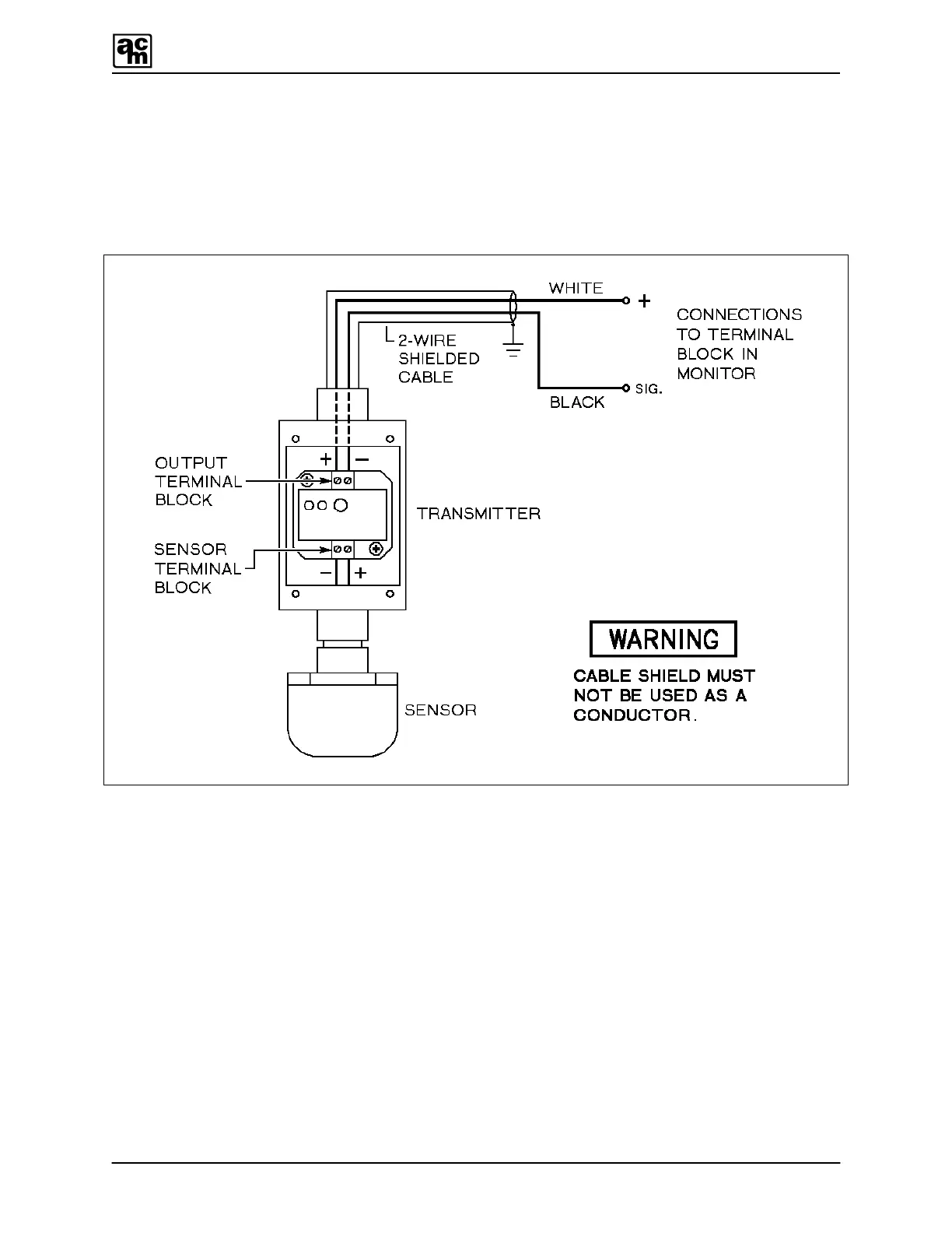
4.3 TRANSMITTER TO MONITOR WIRING
The transmitter output (–,+) terminals connect to the (SIG,+) terminals on a channel terminal
block of the monitor (one transmitter per channel), as shown in FIGURE 3. Each transmitter
MUST BE CONNECTED TO ITS CORRESPONDING CHANNEL to retain factory calibration.
FIGURE 3: Transmitter to monitor wiring.
4.3.1 INTERFACING TO COMPUTER, DATALOGGER, OR NON-AMC MONITOR
All Armstrong sensor/transmitters can be connected to computers or dataloggers through
analog-to-digital converters, or to non-AMC monitors. The transmitter output (–,+) terminals
connect to a filtered 12 to 30 VDC power supply, through field wiring (See FIGURE 4).
The signal output from the transmitter is a 4 to 20 milliamp DC current. This signal can be
measured or recorded anywhere in the supply loop if required, or if a voltage measurement is
needed, connect a resistor (see FIGURE 4) between the transmitter's negative (–) output
terminal and the negative or common (–) of the power supply.
 Loading...