AMC-200 Transmitter
3
4.2 CABLE SELECTION AND WIRING
Connection should be made using 2-conductor, shielded cable. For best signal transmission
and maximum noise rejection, run cable through steel conduit (cable shield must be grounded
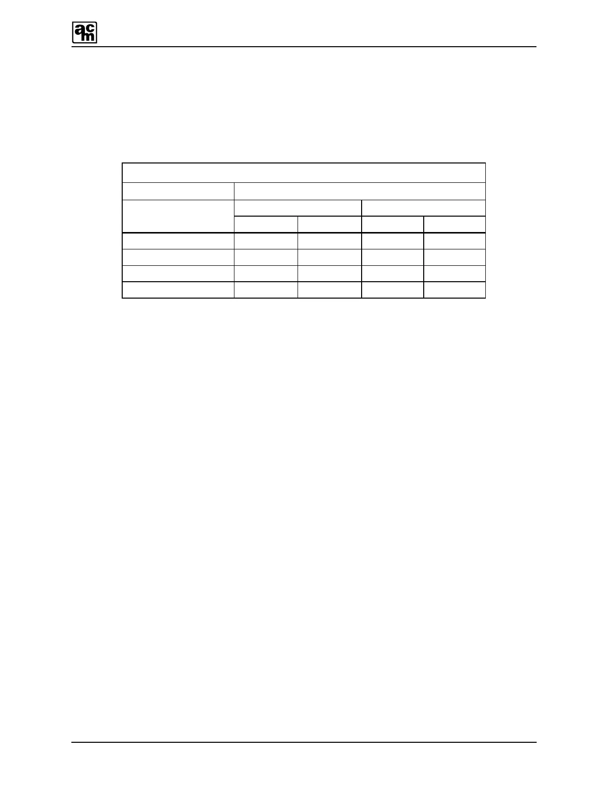
at the monitor or power supply). For basic cable selection (between monitor and transmitter)
when using a 250 ohm load resistance, use the following chart:
Cable Selection Chart
Wire Gauge Cable Length
Feet Metres
AWG
@ 12VDC @ 24VDC @ 12VDC @ 24VDC
22 1000 15000 305 4732
20 1500 23000 457 7010
18 2500 38000 762 11582
16 3800 57000 1158 17373
For applications not covered by the above chart, an example is shown below for selecting the
right cable, using the graph in FIGURE 2 and the following formulas (Remember that some non-
AMC equipment may have the load resistance built-in).
EXAMPLE: (Refer to FIGURE 2)
Known data: Obtained from measurements, ratings or specifications.
Power supply ........................................ 17 VDC
Load resistance .................................... 180 Ohms
Wire gauge ........................................... 20 AWG
Cable length / 1 Ohm resistance ...…... 43.6ft (13.3m) typical
Calculations on the graph: Using the power supply voltage as reference.
Maximum resistance .…... MR
Load resistance ............... LR
Formula 1: To determine remaining safe loop resistance.
Maximum resistance ……. 518 Ohms
Load resistance …………. – 180 Ohms
Remaining resistance ….. = 338 Ohms
Formula 2: To determine maximum safe cable length allowed.
Remaining resistance ………… 338 Ohms
Cable length (for 1 Ohm) …….. x 43.6 Feet
Maximum safe cable length …. = 14736 Feet
 Loading...