14
This will automatically invoke the TRI tuning aid and will insert the input attenuator (the ATT LED will
light) after one second. The attenuator will be switched off, and the old screen will be returned
automatically, after you release the PTT shortly. If you have achieved meanwhile a nearly good tuning,
the attenuator would not be inserted again. If the old screen was the same (TRI, selected manually
earlier), youll then be able to precisely tune the amplifier also at nominal power, without changing drive
at all. Use this hint to shorten the tuning process duration.
c) Tuning Procedure.
While a continuous (CW) signal at the desired frequency is still applied:
- Look at the upper scale (forward power); obtain maximum power using the upper (TUNE) knob;
- Look at the lower (Load Cap) scale and turn the lower (LOAD) knob in order to center the triangle
marker at the ! mark.
- Release the PTT shortly in order to disable the attenuator, then repeat both steps at nominal power.
Always finish by peaking with the TUNE knob.
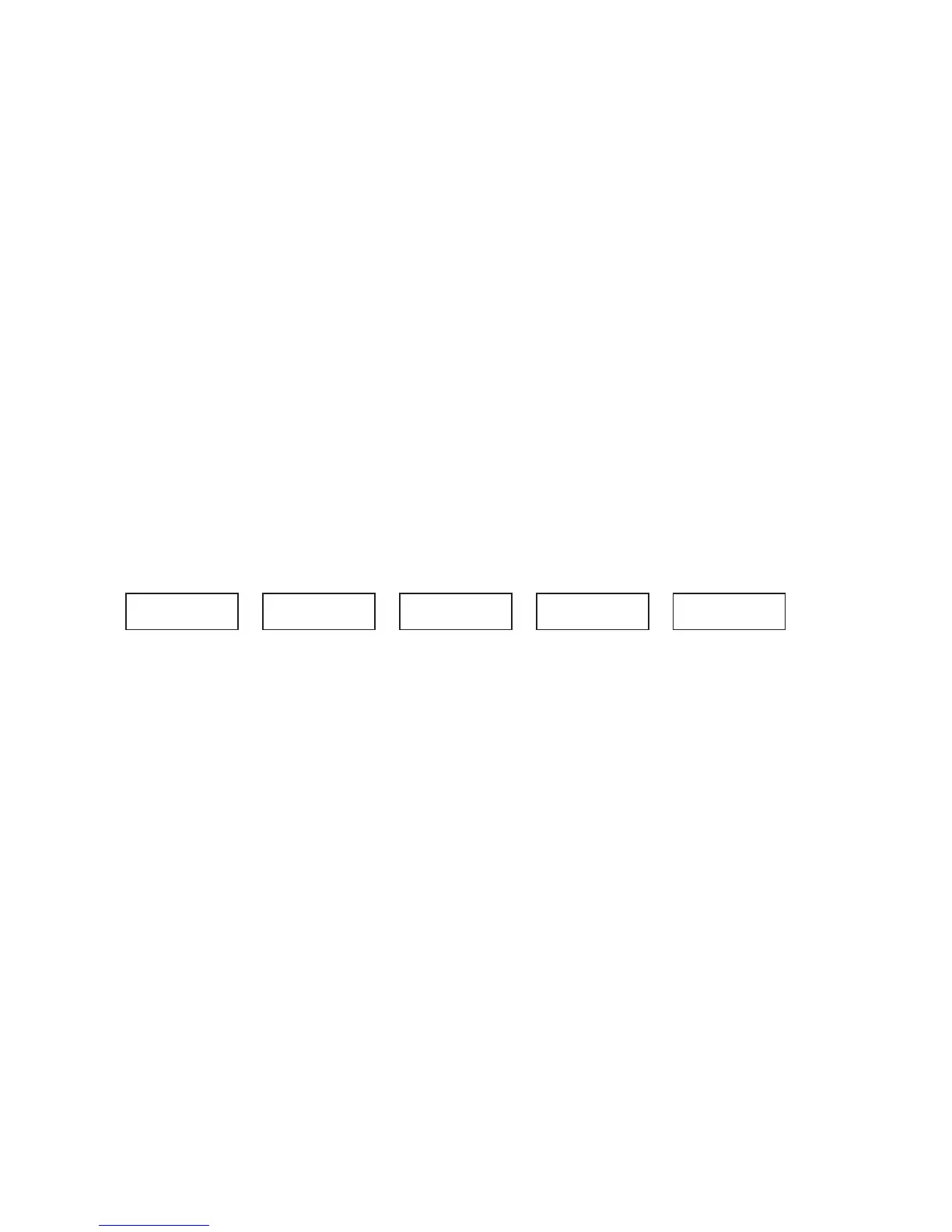
N O T E
Appearance of an arrow on either left or right TRI scale edges means that the LOAD
knob is too far from the proper position. To correct for this, turn the LOAD knob to
the prompted direction until the triangle marker appears inside the scale field.
I
_____
!
_____
IIII
____>
!
_____
IIIIIIIIIII
_____
!
<____
IIIIIII
_____
!
___v__
IIIIIIIIIIIIIIII
_____
v
_____
:rekramon
rofbonkENUTesu
ynategotP.xam
.rekram
:tfelrafasirekram
bonkDAOLnrut
litnuthgirotretniop
.edisnirekram
:thgirrafasirekram
bonkDAOLnrut
litnutfelotretniop
.edisnirekram
:edisnirekram
bonkDAOLnrut
ottfelylthgils
.tiretnec
:denutsiDAOL
otbonkENUTnrut
drawroFkaep
.hsinif&rewoP
Fig. 4-1. Using TRI tuning aid
Please note also, that the TRI mark will not appear until at least 5W drive is applied, and at least 20W
forward power is achieved.
If, for some reason, matching cannot be accomplished successfully, check BAND switch and antenna
selection. Then check the antenna VSWR at same drive frequency.
d) Tuning hints.
While turning knobs, youll note that both tunings would be virtually independent. This is a benefit of
the TRI. The plate-load resistance increases to the right and decreases to the left of the TRI center.
The center of the scale corresponds to the proper LOAD capacitor tuning, which presents an optimum
load resistance to the tube.
If you tune to the right, youll obtain more gain, but less undistorted output power will be attainable.
You may prefer to use this hint when your drive power is insufficient or when you need less output but
better efficiency, for instance at heavy duty modes (RTTY, SSTV etc) where less heat is wanted.
Tuning to the left of the center would lead to the opposite: less gain and more power attainable. Of
course, this requires more drive power, more plate current, and more plate heat, which shortens
tubes-expected life, as its cathode would be faster exhausted.

 Loading...


