6
2. INSTALLATION
2-1. Unpacking and Initial Inspection
N O T E
Before you start to install the amplifier, thoroughly read this manual. First, carefully
inspect the cardboard carton and its contents for physical damage. If damage is
noticed, notify your dealer immediately. Delay may infringe carriers warranty
conditions. Keep all packing for possible future transportation!
2-2. Line Voltage Selection
C A U T I O N
To avoid damage (not covered under warranty), check carefully if the voltage for
which the amplifier is set corresponds to your mains nominal voltage.
Normally the amplifier is supplied set for a nominal line voltage of 240V. There might be exceptions in
cases of special delivery and then the voltage set is noted in the Table of Individual Data (Table 2-1). If
your power line has a different nominal voltage, it will be necessary for you to contact your dealer.
AMP s/n
Tube s/n
Voltage Selector VAC
Table 2-1. ACOM 1000 Individual Data
2-3. Amplifier Location Selection
C A U T I O N
The weight of the unit is about 22kg, which should preferably be handled by two
persons.
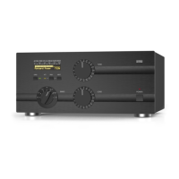
Position the amplifier near the place where it will be used. Youll need an easy access to the command
knobs and indicators area, as well as to the rear panel cabling.
No magnetic-field sensitive devices should be located next to the right side of the amplifier as its power
transformer is located there. Its best to position it to the right of your transceiver. No temperature
sensitive devices should be located above the exhaust hot air area, so dont push it under a shelf. You
may prefer to use the bottom scales of both variable capacitor knobs (TUNE and LOAD) if you install
it on a shelf. DO NOT OBSTRUCT AIR INTAKE (rear panel) and EXHAUST (top cover) areas of the
amplifier. Keep a minimum distance of 10cm (4 inches) to the intake and 50cm (20 inches) to the
exhaust.

 Loading...