3
1. GENERAL INFORMATION
1-1. Introduction and Description
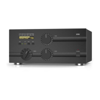
This manual explains the installation, operation, and maintenance of the ACOM1000 HF+6 meters
linear amplifier.
The ACOM1000 is a complete and self-contained linear amplifier that covers all amateurs bands from
1.8 through 54MHz and provides over 1000W-output power with less than 60W-exciter drive. Antenna
VSWR up to 3:1 is acceptable at full power. Tuning is substantially simplified by a plate-load True Resistance
Indicator (TRI) and by an automatically controlled input attenuator. Operating parameters are displayed
by a multi-functional backlighted Liquid Crystal Display. Full break-in transmit/receive switching (QSK)
is standard.
1-2. Owner Assistance
If assistance is needed, you should contact your local dealer first. If you still have an issue you need to
discuss with one of ACOMs specialists, the contact information is as follows: fax + 359 2 920 96 56,
tel. + 359 2 920 96 55, e-mail acom@mail.orbitel.bg or acom@aster.net or by mail: bul. Gornobanski
Nr.151, 1330 Sofia, Bulgaria.
1-3. Equipment Supplied
The ACOM1000 amplifier and this manual are shipped in a cardboard carton.
1-4. Features
l Easy to operate. The TRI is a powerful tuning aid which, together with the automatically controlled
input attenuator, helps the operator to quickly and precisely match antennas (5-10 seconds typically).
The auto-operate function (when enabled) maintains the amplifier in OPERATE mode for you, thus
saving manual operations and time.
l No heavy outboard antenna tuners required for antenna VSWR up to 3:1 (and higher on some
bands). Your amplifier will perform the functions of an antenna tuner, thus enabling you to change
antennas faster and use them over a wider frequency range (saving tuning time).
l An amplifier that is both user-friendly, and that looks after itself. It is designed to safely withstand up
to 500W reflected power, up to 100 milliseconds duration of drive spikes, drive RF tails after a PTT
or KEY release, operators inadvertent tuning errors etc. It would also not cease to function with a
soft AC line and would deliver more than half power at only 75% of nominal mains voltage. It would
withstand up to 10 milliseconds (down to zero) voltage drops, and up to +15% line voltage spikes,
which is important particularly when used at field days, DXpeditions, and other portable events.
l LCD comment display. All amplifier status indications are explained via detailed text displayed on
the dot matrix backlighted liquid crystal display (LCD). The upper-lines strip on the LCD always reads
directly peak forward power. LED indicators are provided for OPERATE, attenuation-on, and
ON/OFF conditions.
l Easy maintenance. Signatures of the amplifier internal status are stored in a nonvolatile memory for
7 most recent auto protection trips. This information can be forwarded to your dealer for diagnostics.
Using an EXCEL APPLICATION (available from ACOM or your dealer free of charge) and a PC you can

 Loading...