A single Svetlana 4CX800A (GU74B) high-performance ceramic-metal tetrode is used in the amplifier.
Replacement is a complex and potentially dangerous operation that involves adjustment of the plate idling
current. This should not be attempted by the user. Contact your ACOM dealer.
5-4. Simplified Schematic Diagram
See Fig. 5-1 ACOM1010 Simplified* Schematic Diagram. The 4CX800A (GU74B) Svetlana high
performance ceramic-metal tetrode (V1) with plate dissipation of 800 W is grid-driven. The input
signal from the RF INPUT jack is passed through a broadband input matching circuit, which consists of
components on the INPUT PCB and includes the drive-power swamping resistor Rsw. This circuit tunes
out the input capacitance of the tube. The swamping resistor Rsw is a termination load for the matching
circuit and can dissipate up to 80 W of RF drive power. It also eliminates any tendency toward oscillation
by the tube, ensuring excellent RF stability of the amplifier.
The cathode resistor Rc creates DC and RF negative feedback, thus stabilizing gain and equalizing
frequency response. The combination Lp1-Rp1 in the plate circuit is a VHF/UHF parasitic suppressor.
DC plate voltage is fed through chokes RFC1-RFC2 and the capacitor Cb3 blocks it from the output.
The output tank, comprised of LP1, LP2, LL, CP1, CP2, and CL1-CL3 , form a classic Pi-L network
and suppress harmonic frequency emissions. This circuit is switched and tuned by S1A-S1C and the air
variable capacitors CP1, 2 and CL1, 2. The output signal is fed through the antenna relays K1 or K2 in
the WATTMETER PCB. The WATTMETER PCB also includes a high-pass filter for frequencies below
100 kHz, and it prevents the plate supply from reaching the antenna.
The plate RF voltage is monitored through the capacitor Ca and together with the RF WATTMETER is
the main source of information for the control circuit of the amplifier in evaluating tuning quality. The
control circuit is based on the ATMEGA-8L micro-controller from Atmel. All voltages are delivered from
the line (mains) and HV PCBs. The currents of the control grid, screen grid, and the plate, as well as
the reflected power and tuning quality, etc., are continuously monitored by the micro-controller. Many
software-derived protections are based on this information.
* Detailed electrical schematic diagrams are available from ACOM or from your dealer on request.
Fig.5-1 ACOM1010 Simplified Schematic Diagram
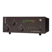
By pressing the OPER and RTTY buttons simultaneously, the upper LED bar-graph is switched to the
service mode, which is indicated by both red bar-graph lights and the yellow
light illuminating. Pressing
buttons together again will select additional service measurement functions.
RTTY buttons together again will select additional service measurement functions. RTTY
Pressing them a final time will return the amplifier to the normal operating mode. These steps are
buttons together. The two red lights on the right side of the upper
RTTY buttons together. The two red lights on the right side of the upper RTTY
bar-graph will illuminate to confirm that the amplifier is in the service mode. The yellow
also illuminate. The upper bar-graph should show a grid 1 current reading no higher than 5 mA (5 LEDs
buttons once again will now illuminate the yellow
RTTY buttons once again will now illuminate the yellow RTTY
provides an approximate reading of grid 2 voltage. The upper bar graph should show a voltage reading
within the range of either 270-300 Volts (9-10 LEDs illuminated) for RTTY or 210-330 Volts (7 to 11
LEDs illuminated) for SSB and CW.