the operator’s choice. It is the operator’s responsibility to connect suitable antennas to the
connectors on the rear panel of the amplifier.
LED illuminates whenever the
TX LED illuminates whenever the TX
input is keyed (closed to ground), i.e., when the
transceiver goes into the transmit mode. See Section 2-4(d).
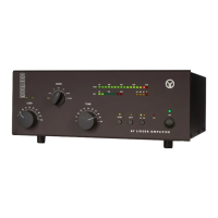
knob controls the band switch, and
are used to adjust their respective
variable air capacitors in the amplifier’s output circuit. The settings of these three controls must be changed
at each band change as well as when an antenna is changed. The three LED indicators located above
are called the “TRI tuning indicator” and they are used to achieve antenna impedance
matching during a re-tune procedure. Please see Section 4-5 for a discussion of the tuning procedure.
To avoid damage not covered by the amplifier’s warranty, do not turn the
switch while transmitting. Switching while transmitting is called “hot switching” and
it will cause irreparable damage to the band switch.
There are three warning LED indicators and one fault LED indicator located in the bar-graphs window.
The following describe the error conditions and the correct responses (except for the service functions
– when illuminated, a control-grid overload condition exists; reduce the drive power for safe
- when illuminated, a screen-grid overload conditions exists; reduce the drive power and/or refresh
the tuning (Section 4-5) for safe operation;
- when illuminated, a plate current overload condition exists; reduce the drive power and/or refresh
the tuning (Section 4-5) for safe operation;
– when illuminated, the amplifier automatic protection has tripped. If
is accompanied with one of
condition indicators, the cause of the protection trip will be evident. When
illuminated, check the keying wiring, Section 2-4(d). See Section 4-6 for details about the auto-protection
Operation of the amplifier is simplified through ACOM’s innovative TRI tuning aid, Auto-Operate function,
and automatic protection systems. To make full use of the amplifier’s potential and to configure it to
local conditions, the following information should be read carefully.
In order to turn on the amplifier, press the
switch at the bottom-right corner of the front panel.
POWER switch at the bottom-right corner of the front panel. POWER
The LED indicator above the switch will glow green and the audible cooling fan will start. Following a
series of automatic self-tests, the
LED will begin to flash green and will continue to do so during
OPER LED will begin to flash green and will continue to do so during OPER
the 150-second warm-up period. Throughout this period, the amplifier will remain in the standby mode,
and the transceiver may continue to be used. Also during this period, the
to change antennas, i.e., between the antennas connected to the
panel of the amplifier. Switching between the antennas does not affect the warm-up process.