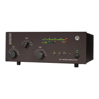
Fig. 3-1 ACOM1010 Display and Control
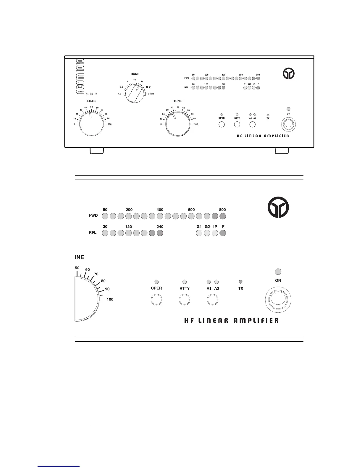
Fig. 3-2 ACOM1010 Display Window
Note that the upper LED bar-graph always reads peak forward power, except for the service functions
(Section 5-5). The 800 W-scale resolution is 50 W. Note also that levels below 50 W may be not
The lower LED bar-graph will indicate reflected power up to 240 W. The scale resolution is 30 W.
The OPER button alternatively switches between the operate and standby modes once the amplifier has
completed its 150-second warm-up period. See Section 4-2.
button reduces the output power of the amplifier to 500 W. See Section 4-3. The button
RTTY button reduces the output power of the amplifier to 500 W. See Section 4-3. The button RTTY
labeled A1-A2 (Section 4-4) changes the antenna output to either antenna 1 or antenna 2, according to