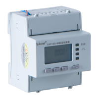
4.3.1 Instrument terminal block and wiring method
1 2
L(+)N(-)
POWER
40 49 42
DO1 COM1DO2
Relay Outputs
30 31 39 32 33 21 22
DI1 DI2 BAIO3 IO4
Switching Inputs
Common
RS485
11 14
Voltage input
Current input
4 5
U1 UN I1* I1
three-phase single-phase
Figure 7 AMC72 series terminal block diagram
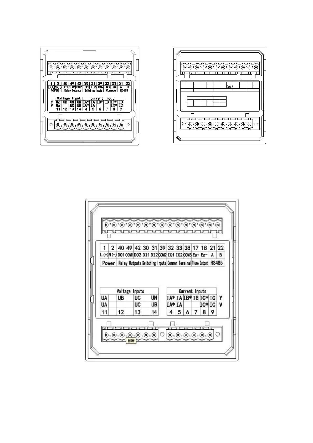
Note: Switching input: 32 - DI3, 33 - DI4;
pulse output: 32 - E +, 33 - E-.
Analog output:32-AO,33-COM3.
Figure 8 AMC96 series terminal block diagram
Note:
Switching input: 32——DI3, 33——DI4, 38——COM3;
pulse output: 32——AO1,33——AO2,38——COM3.

 Loading...