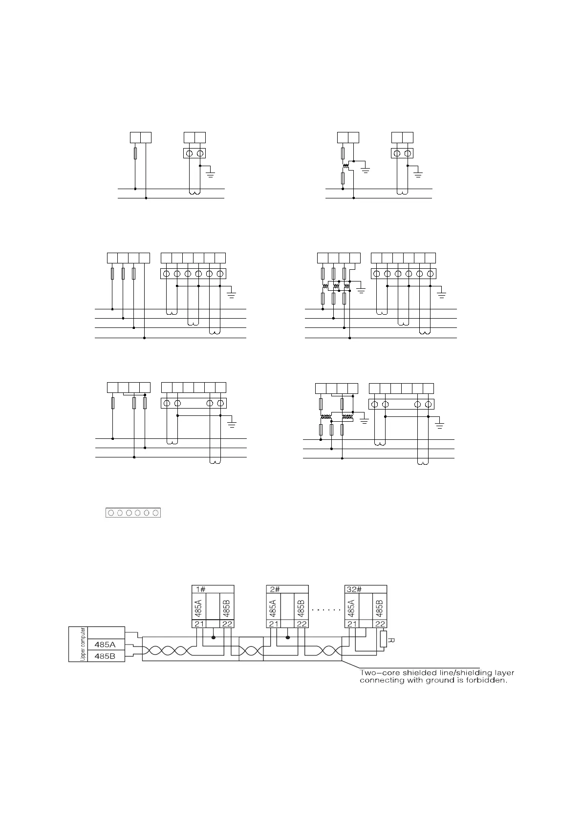
4.2.2 Instrument signal terminal wiring method
Signal terminal: "4,5,6,7,8,9" is the terminal number of the current input; "11,12,13,14" is the terminal
number of the voltage input.
A
B
C
N
UA UB UC UN IA
*
IA IB
*
IB IC
*
IC
FUSES
A
B
C
N
UA UB UC UN IA
*
IA IB
*
IB IC
*
IC
FUSES
A
B
C
UA UB UC UN IA
*
IA IB
*
IB IC
*
IC
FUSES
3-phase-4-wire 3CT
3-phase-4-wire 3PT、3CT
3-phase-3-wire 2PT、2CT
S1 S2
S1 S2
S1
S2
S1 S2
S1 S2
S1
S2
S1 S2
S1
S2
* * * * * *
* * *
*
*
*
*
*
*
*
*
A
B
C
UA UB UC UN IA
*
IA IB
*
IB IC
*
IC
FUSES
3-phase-3-wire 2CT
S1 S2
S1 S2
* * *
*
*
11 12 13 14 4 5 6 7 8 9
11 12 13 14 4 5 6 7 8 9
11 12 13 14 4 5 6 7 8 9
11 12 13 14 4 5 6 7 8 9
L
N
U1 UN I1
*
I1
FUSES
S1 S2
*
*
11 14 4 5
L
N
U1 UN I1
*
I1
FUSES
S1 S2
*
*
11 14 4 5
Single-phase:
Single-phase-2-wire 1CT
Single-phase-2-wire 1PT、1CT
Three-phase
is the test terminal for CT secondary side short circuit.
NOTE:
Figure 9 Schematic diagram of instrument signal wiring
Note: is the test terminal for short circuit of CT secondary side.
An example of wiring for the communication part is shown below:
Correct wiring method: the communication cable shield is connected to the earth.
Figure 10 RS485 communication wiring diagram
It is recommended to add a matching resistor between A and B of the end meter, and the resistance range is
120Ω~10 kΩ.

 Loading...