33
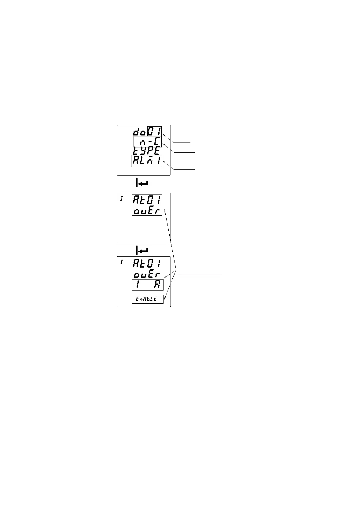
generated , do1 will act.
② When the output control mode of do1 is selected as ALM (ALM1 or ALM2) and associated (ENABLE) with Phase A
overcurrent alarm and Phase A overpower alarm and not associated (DISABLE) with the other alarms. After the
setting is completed, do1 acts when Phase A overcurrent or Phase A overpower alarm occurs.
③
Before selecting the alarm type associated with do, make sure that the alarm type is enabled in the alarm setting. If it
is not enabled, the do does not act when this alarm condition occurs.
DO number
Initial state
Control mode
DOx is associated with overcurrent
alarm-phase A overcurrent alarm
7.5.10 Analog input setting (valid with analog module)
1. Press ◀▶ until Aio is selected and press the Enter key.
2. Press
◀▶
until Ai is selected and press the Enter key.
3. Press ◀▶ until the Ai channel to be modified is selected and press the Enter key.
4. Select the input type (make sure the input type is current input or voltage input, current input can choose 0-20mA, 4-20mA, voltage
input can choose 0-5V, 1-5V). Press the Enter key.
5. Select the decimal point of display and press the Enter key.
6. Set the high value of the signal input corresponding to displayed value and press the Enter key.
7. Set the low value of the signal input corresponding to displayed value and press the Enter key.
8. Press the SET button to return.
For example: Ai1 is set to 4-20mA input and the decimal point is set to 1. The displayed value of high point of is set to 1000 and
the displayed value of low point is set to 0. When the Ai1 signal input is 20mA, the displayed value is 100.0. When the signal input is
4mA, the displayed value is 0. When the signal input is 12mA, the displayed value is 50.0.
 Loading...