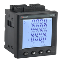
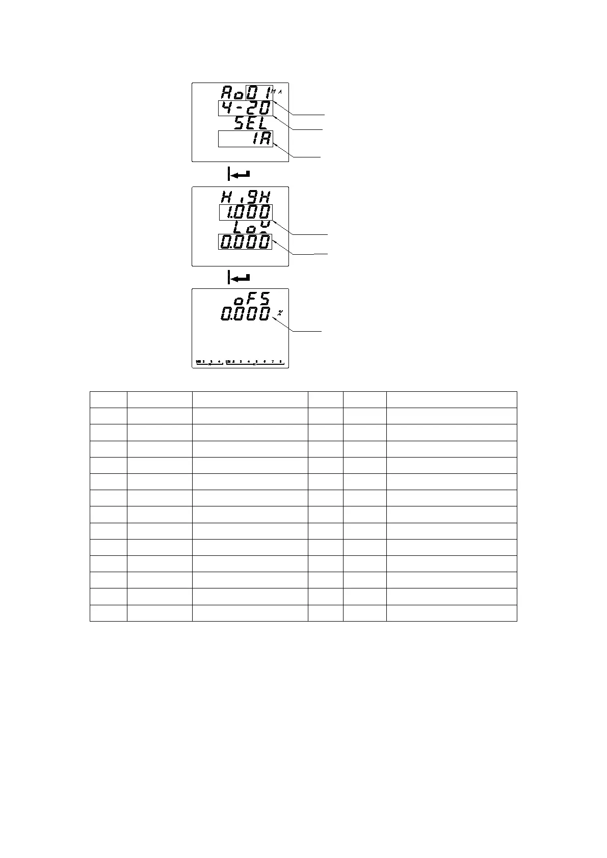
EasyManuals Logo

Acrel APM Series User Manual

Acrel APM Series
77 pages
To Next Page IconTo Next Page
To Previous Page IconTo Previous Page
Page #38 background imageLoading...
Page #38 background image
35
Ao number
Selected signal
Type of output
The corresponding displayed value
of low point of the signal output
The corresponding displayed value
of high point of the signal output
Offset
Table 3: Output Signals
No.
Symbol
Instruction
No.
Symbol
Instruction
0
IA
Phase A current
13
QA
Phase A reactive power
1
IB
Phase B current
14
QB
Phase B reactive power
2
IC
Phase C current
15
QC
Phase C reactive power
3
UA
Phase A voltage
16
QT
Total reactive power
4
UB
Phase B voltage
17
SA
Phase A apparent power
5
UC
Phase C voltage
18
SB
Phase B apparent power
6
UAB
Phase AB line voltage
19
SC
Phase C apparent power
7
UBC
Phase BC line voltage
20
ST
Total apparent power
8
UCA
Phase CA line voltage
21
PFA
Phase A power factor
9
PA
Phase A active power
22
PFB
Phase B power factor
10
PB
Phase B active power
23
PFC
Phase C power factor
11
PC
Phase C active power
24
PF
Total power factor
12
PT
Total active power
25
F
Frequency
For example:
When Ao1 is set to 4-20mA output, the signal is selected as IA (Phase A current), the corresponding signal of output high point is
5.000A, and the corresponding signal of output low point is 0.000A. When Phase A current value is 5A, Ao1 output is 20mA; when
Phase A current value is 0A, Ao1 output is 4mA; when Phase A current value is 2.5A, Ao1 output is 12mA. If the actual output is
3.99mA at 0A, then the offset can be set to (4-3.99)/16 = 0.062% to make the zero output be 4mA.

Questions and Answers:

Question and Answer IconNeed help?

Do you have a question about the Acrel APM Series and is the answer not in the manual?

Acrel APM Series Specifications

General IconGeneral
BrandAcrel
ModelAPM Series
CategoryMeasuring Instruments
LanguageEnglish

Related product manuals