Ultrasonic flaw detector А1212 MASTER
Operation Manual
27
ACOUSTIC
CONTROL
SYSTEMS
2
Key Description
Change gain (amplification)
Change the length of the strobe with reference to its le boundary
Move the strobe to the le/right
Add the anchor point in the cursor position
F6
Delete the anchor point
Confirm new TCG settings
Exit the TCG settings mode
Table 10
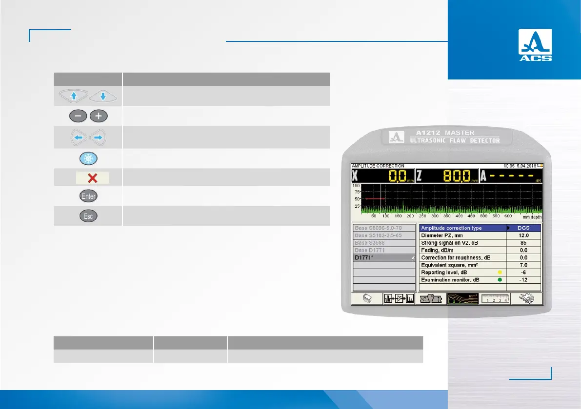
2.3.1.4.2 Adjustment of amplitude correction DGS
The instrument is equipped with an option of generation of the specific DGS diagrams of
the single-crystal transducers.
DGS diagrams are designed to adjust the sensitivity of the device during testing and for
automatic calculation of the equivalent area of the flaw.
The screen when setting the DGS parameters is presented in the Figure 19.
The names of the DGS parameters and their permissible values are presented in the Table 11.
Figure 19
Parameter name Value Description
Type of the amplitude correction DGS DGS was selected in the function of amplitude correction
Table 11
▼
 Loading...