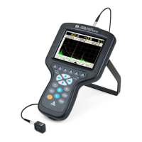
Ultrasonic flaw detector А1212 MASTER
Operation Manual
28
ACOUSTIC
CONTROL
SYSTEMS
2
Parameter name Value Description
Diameter of piezoelectric
element, mm
from 0.0 to 25.0 with
step 0.1
Diameter of the piezoelectric element is presented in the Certif-
icate on the PT or shall be measured independently by the user
Reference signal for V2, dB
from 0 to 200 with
step 1
For angle beam PTs
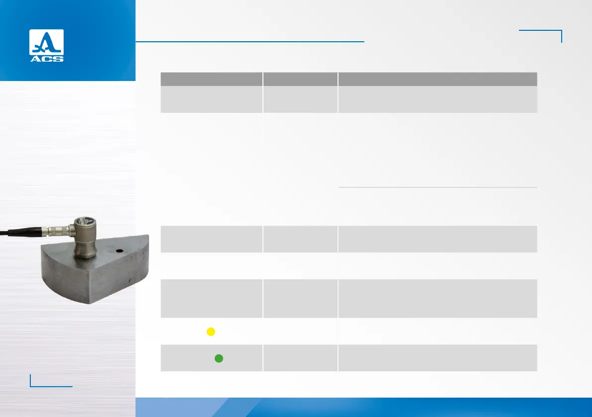
the amplitude of the signal from the cylindrical 5 mm hole in
the V2/25 sample shall be determined (Figure 11):
-by large contact surface, if angle of incident is less than or
equal to 62˚;
- by small contact surface, if angle of incident exceeds 62˚
For straight beam PTs
the amplitude of the bottom signal, when the PT is set on the side
surface of the V2/25 sample, shall be determined (Figure 20)
Attenuation, dB/m
from 0.0 to 99.9 with
step 0.1
Setting the attenuation coefficient in the material (specified in
the ultrasonic testing guidelines)
Correction for roughness, dB
from 0.0 to + 12.0 with
step 0.1
Correction for sensitivity level, considering the difference
between roughness and undulation of the surface
Equivalent area, mm
2
from 0.0 to 25.0 with
step 0.1
Value of acceptance equivalent area of the reference reflector
determines the DGS curve of the acceptance level
(specified in the ultrasonic testing guidelines)
Reference, dB
from – 12 to 0
Setting the reporting sensitivity level with reference to the
acceptance level
Search AFAS, dB
from – 12 to 0
Setting the reporting sensitivity level with reference to the
acceptance level
Table 11
▼
Figure 20
 Loading...