Ultrasonic flaw detector А1212 MASTER
Operation Manual
34
ACOUSTIC
CONTROL
SYSTEMS
2
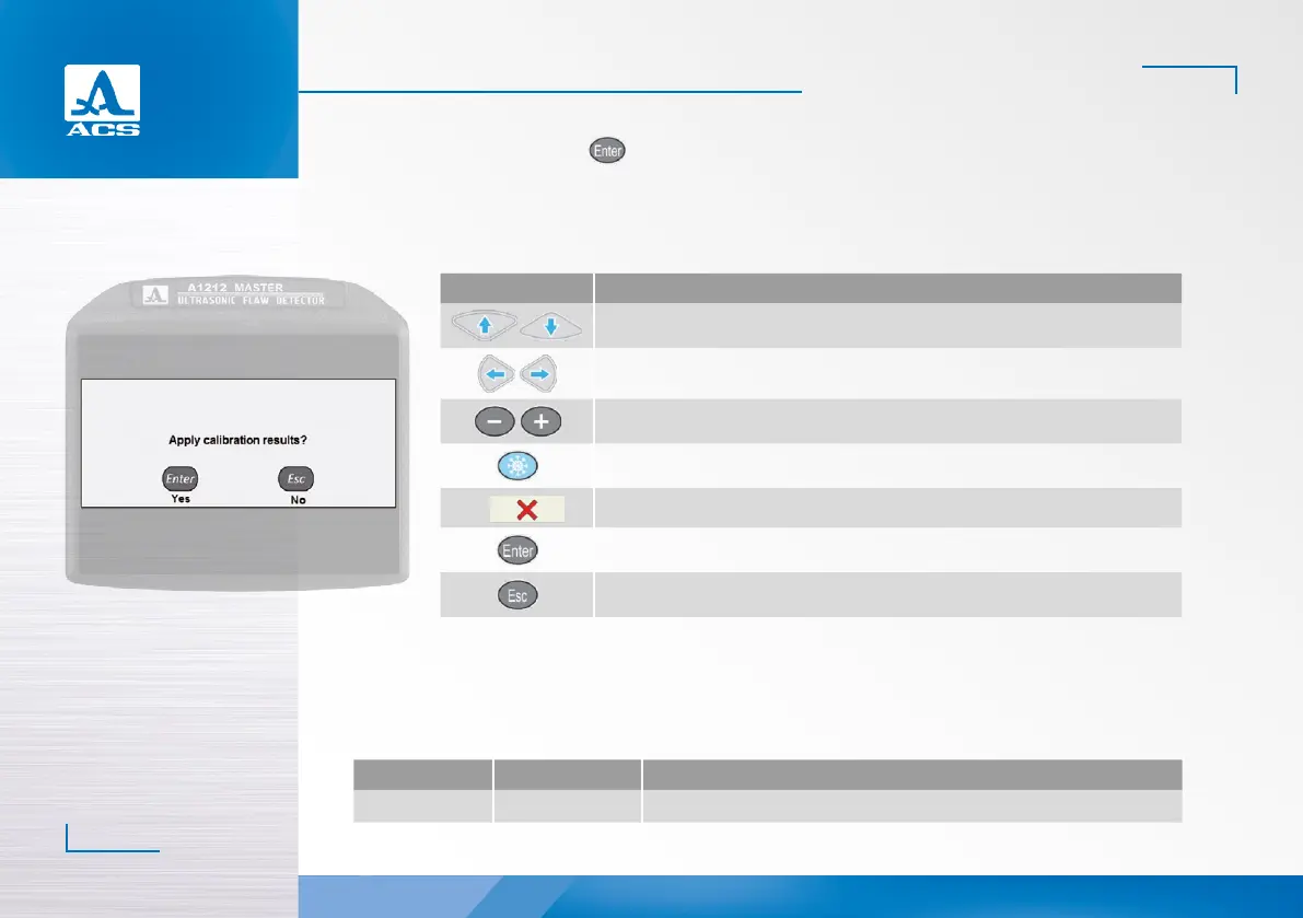
To save the settings, press the key. Confirmation window of new DAC settings will be opened (Figure 29).
If new settings are confirmed, then three DAC curves will be displayed on the screen aer exiting the SETTING mode, these
correspond to acceptance, reporting and search levels (Figure 30).
The functions of the keys applicable for DAC adjustment are presented in the Table 14.
Figure 29
Table 14
Key Description
Adjustment of gain (amplification)
Move the strobe to the le/right
Change the length of the strobe with reference to its le boundary
Set the anchor point
F6
Delete the anchor point
Exits the DGS settings mode
Opens a confirmation window of new DGS settings
2.3.1.5 Editing the imaging parameters
The screen when setting the imaging parameters is presented in the Figure 31.
The names of the parameters of the tested object and their permissible values are presented in the Table 15.
Table 15
Parameter name Value Description
Sweep scale mm / mm depth / µs Selects units of the horizontal scale which determine the signal display parameter
 Loading...