Copyright © 2016 Access Control Technology Ltd. Part No. 18-00099 Issue 1.0
4
ACTpro 1520e and ACTpro 1500e Operating & Installation Instructions
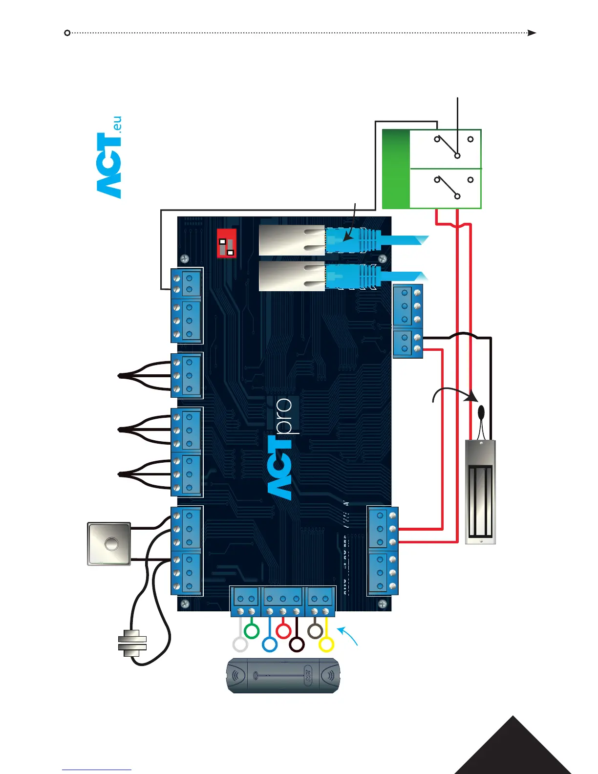
1.0 Typical wiring of ACTpro 1520e/1500e
RS485
BREAK GLASS UNIT
(Double Pole)
POLE A POLE B
DOOR
NETWORKS
DOOR
CONTACT
CONTROLLER
NETWORK
NC
C
NO
NC
C
NO
OP3
OP2
0V
AUX I
DC
PB
A
B
0V
A
B
0V
A
B
OV
0V
+12V
MAINS
PRESENT
B/GL
TAMP
IN OUT
2-16 DOORS 17-32 CTRL NW
1520e
WIRING DIAGRAM
W
G
B
R
BK
BN
Y
ACT READER WIRE
NC
NO
C
NC
NO
C
12V 0V
0V PSU
IMPORTANT:
Place varistor across all lock terminals
Diagram shows normally energised Magnetic Lock
PUSH TO EXIT
RS485
Break Glass Monitoring
Normally Closed
ETHERNET: RJ45
To next IP controller or IP device.
Must be configured with correct
IP address.
RED
GREEN
DATA
+12V
OV
SENSE
CLOCK
Normally
Open
Normally
Closed
EXIT READERS
For Clock & Data readers, wire
exit readers in parallel but leave
the sense line unconnected.
For Wiegand readers, wire the
DATA 0 of the exit reader to SENSE
on the ACTpro 1520e.
Max length 100m with 12V DC
Cable: 8 Core Screened
Belden 9504 or equivalent