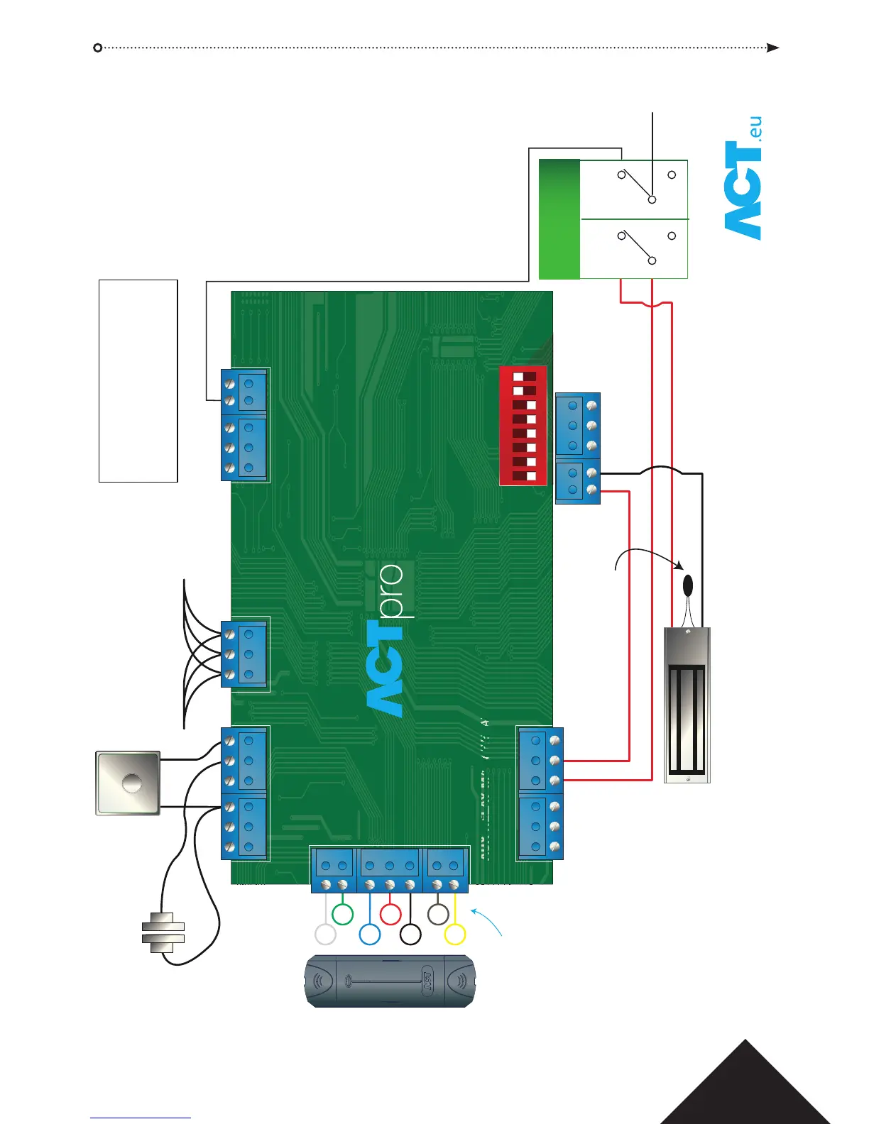
PUSH TO EXIT
RS485
Break Glass Monitoring
Normally Closed
RED
GREEN
DATA
+12V
OV
SENSE
CLOCK
Normally
Open
Normally
Closed
1 2 3 4 5 6 7 8
ON DIP
Please Note:
If the Mains Present, Door Contact or
Break Glass Inputs are not used, they
should be linked to 0V or disabled via
software.
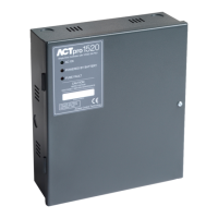
The Blue Comms OK LED is on while
ACTpro 120e is communicating with
the controller.
Red Fault LED illuminates on:
1. Tamper
2. Break Glass
3. Comms Ofine
4. Mains Fault
5. Voltage Low
6. Current Limiting Fuse (500mA)
FACTORY DEFAULT
This unit should be reset to its
factory default condition before
installation.
To do this, power the unit up with
ALL 8 DIP switches in OFF position.
The unit will beep after 3 seconds.
The unit is now defaulted.
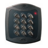
EXIT READERS
For Clock & Data readers, wire
exit readers in parallel but leave
the sense line unconnected.
For Wiegand readers, wire the
DATA 0 of the exit reader to SENSE
on the ACTpro 100e.
Max length 100m with 12V DC
Cable: 8 Core Screened
Belden 9504 or equivalent
From Previous
Door Station/Controller
To Next
Door Station
ACTpro 120e PSU Operating and Installation Manual