OMRON
5A 250VAC
5A 30VDC
+
OMRON
1A 125VAC
1A 30VDC
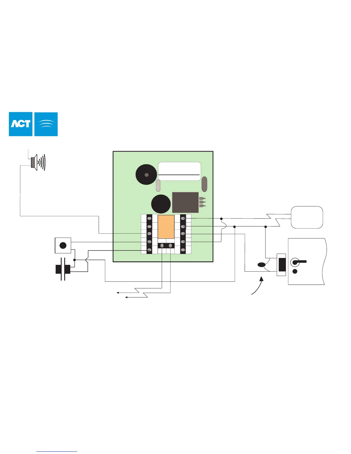
Door
Contact
Door Release Button
12-24V
DC/AC
0V
N/
O
COMM
N/C
B
A
Aux I/O 2
Tamper
This illustration shows wiring
for normally de-energised locks.
If normally energised locks are
required, use the N/C relay contact.
0 1 2 3 4 5 6 7 8 9
BATCH:
PRODUCT :
SERIAL NUMBER :
01XX-
ACTSmart REV1.3
00XXX
Important!
Always Place Varistor
Across Lock Terminals
Volt-Free
Tamper Contacts
+12V
0V
Power
Supply Unit
+V
Sounder
The Aux I/O Output is an open
collector output capable of
sinking 100mAmps.
Note: To program the various Input and
Output operations for the ACTSmart unit,
please refer to page 10.
Aux I/O 1
Default configuration for
AUX I/O 1 is Door Contact.
SCH
RACK
12V = DC
5A/250V ~AC
Programmable
Input
The ACTSmart may be powered
from 12 or 24V AC or DC for
Standalone operation.
Default configuration
for Programmable Input
is Door Release Button.
ACTSmart Standalone Installation Diagram
- 15 -
Default configuration for
AUX I/O 2 is Door Alarm.
- 15 -