Hardware Manual
19
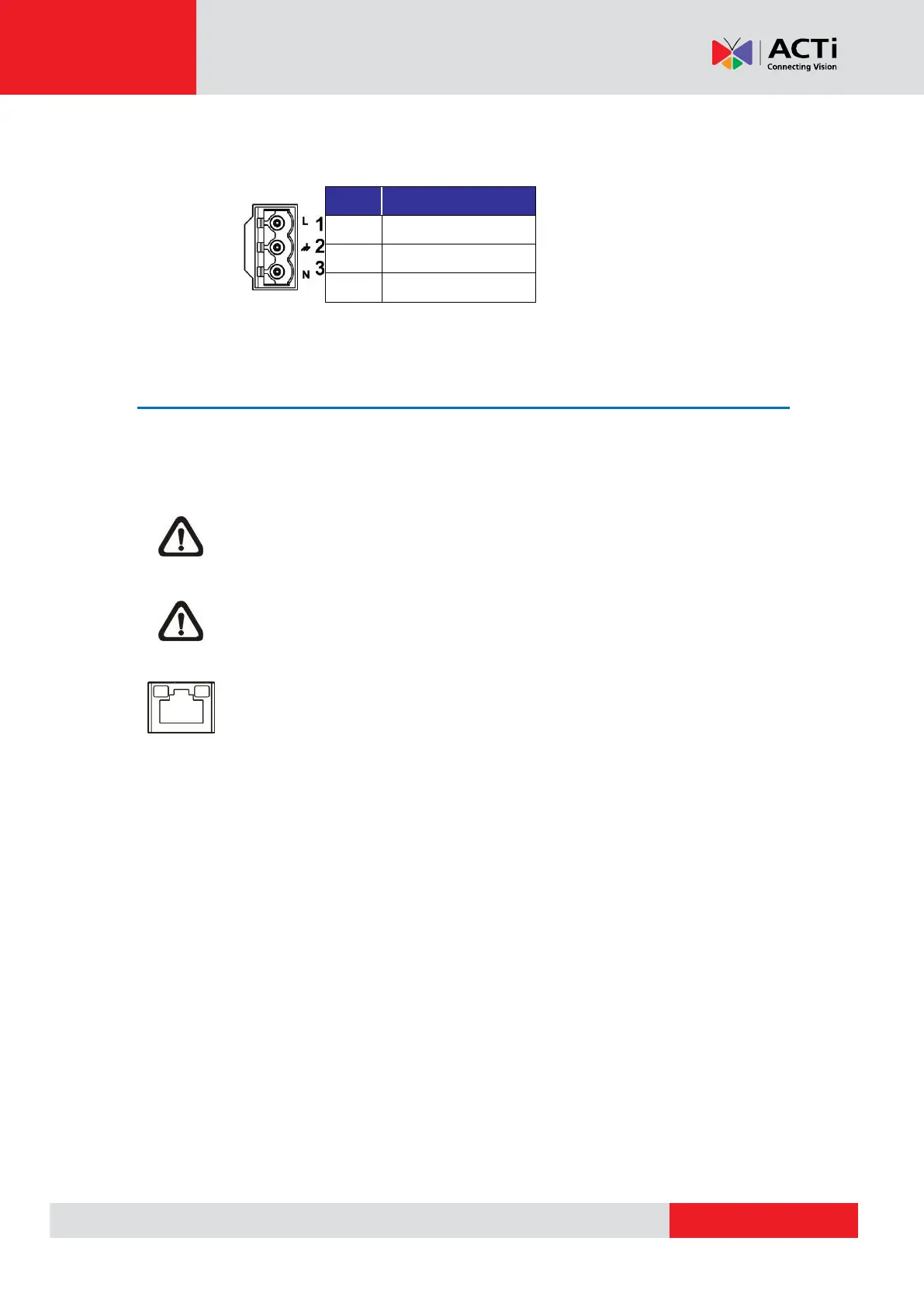
AC24V
Refer to the diagram and pin definition below for AC24V power connection.
Ethernet Cable Connection
To connect one end of the Ethernet cable to the RJ-45 connector of the camera, and plug the
other end of the cable to the network switch or PC.
NOTE: In some cases, Ethernet crossover cable might be needed when connecting
the camera directly to the PC.
NOTE: Check the status of the link indicator and activity indicator LEDs. If the LEDs
are unlit, please check the LAN connection.
Green Link Light indicates good network connection.
Orange Activity Light flashes for network activity indication.