KCM-7111 Hardware User’s Manual
9
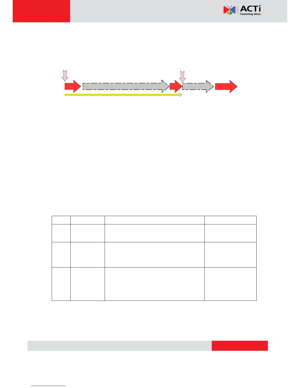
reset button. This length of time fluctuates slightly with the environment. The Power LED light
will come back on and stay on after a few more seconds. The unit will start up with factory
default settings automatically.
On (3s)
On
1s
Power On
About 20 Seconds
Stay On
Off (about 15s)
Off (10~15s)
Restore to Default
Complete
5) Digital Input / Output
Used in applications like motion detection, event triggering, time lapse recording, alarm
notifications, etc., the I/O terminal connector provides the interface to:
•2 transistor output - For connecting external devices such as relays and LEDs. Connected
devices can be activated by Output buttons on the Live View page or through video
management software. Connect Pin 2 with 4 or 6 with 8.
•2 Digital Input - An alarm input for connecting devices that can toggle between an open and
closed circuit, for example: PIRs, door/window contacts, glass break detectors, etc. The device
will detect the change in digital input and transmit the signal to video surveillance servers.
Ground. Connect with Pin 3 for DI control loop.
Provides power to external devices with a
maximum current of 100mA.
Voltage: 12V DC,
Max: 1.2W
Connect to GND to activate, or leave floating
(or unconnected) to deactivate.
Must not be exposed
to voltages greater
than 30V DC.
Connect to Pin 2 through external devices for
DO loop. If used with an external relay, a diode
must be connected in parallel with the load for
protection against transient voltages.
Max load = <100mA
Max voltage = 24V DC
(to the transistor)
(Pin 5 – 8 repeats Pin 1-4 for another set of DIO)
Connect input/output devices to the camera as follows:
1. Attach the cables for the device securely to the supplied green connector block.
2. Once cables are connected, push connector block into the terminal connector on camera.