Hardware Manual
20
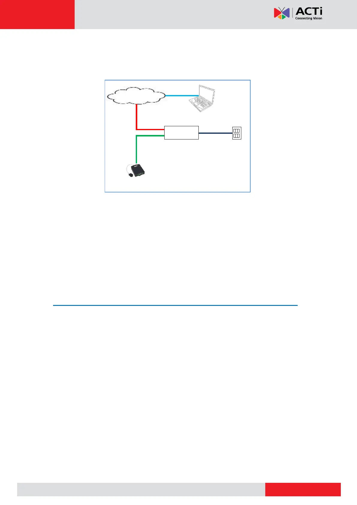
2. Connect the other end to a switch or injector. Then, connect the switch or injector to a
network or PC and a power source. See Power-over-Ethernet (PoE) example connection
diagram below.
PoE Injector /
PoE Switch
Ethernet Cable
(Data + Power)
In case of using a non-PoE switch, power up the camera using a power adapter (not
supplied). See Connecting a Power Adapter (Optional) on page 25 for more
information.
3. As needed, connect and power up other devices, such as digital input/output, audio, or
serial device. See Cable Connections on page 25 for more information on connecting
other devices.
Step 5: Access the Camera Live View
See Accessing the Camera on page 37 for more information.