Hardware Manual
9
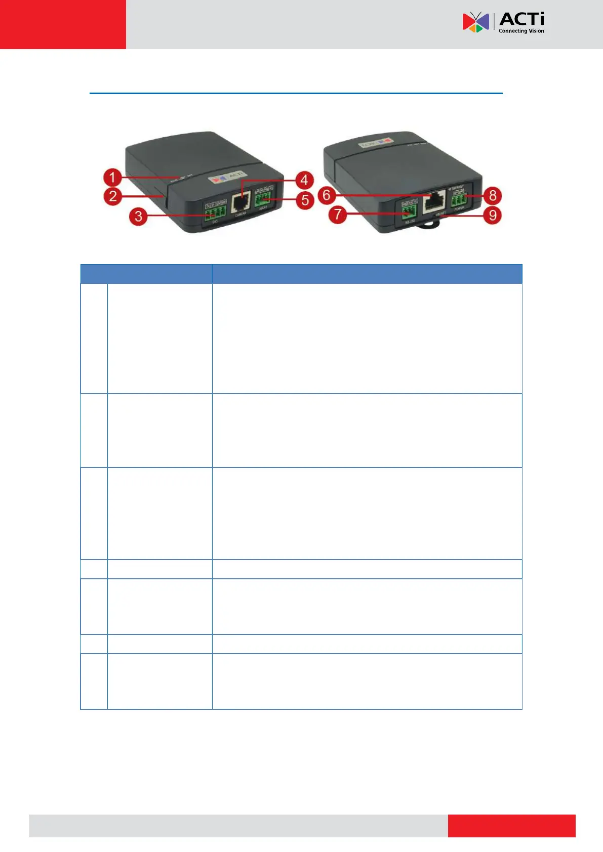
Physical Description
Power LED (PWR): Lights BLUE to indicate power is
connected.
Link LED (LINK): Lights GREEN to indicate network is
connected.
Activity LED (ACT) : Flashes AMBER to indicate network
activity is in progress.
Insert a memory card (not included) into the slot for local recording
purposes. See How to Install / Remove the Memory Card on
page 32.
NOTE: Supports only microSDHC and microSDXC cards.
Connects to digital input or output devices, such as an alarm
trigger, panic button, etc. Digital Input (DI) and Digital Output (DO)
devices are used in applications like motion detection, event
triggering, alarm notifications, etc. See Connecting DI/DO
Devices (Optional) on page 27 for information.
Connects to audio input and output devices, such as microphones
and speakers. See Connecting Audio In / Out Devices
(Optional) on page 30.
Connects to a network using an Ethernet cable.
Connects to serial device using the RS-232 protocol. See
Connecting Serial Devices (Optional) on page 31 for more
informatioin.