Page 29
3.6 Attaching the Rigging Frame
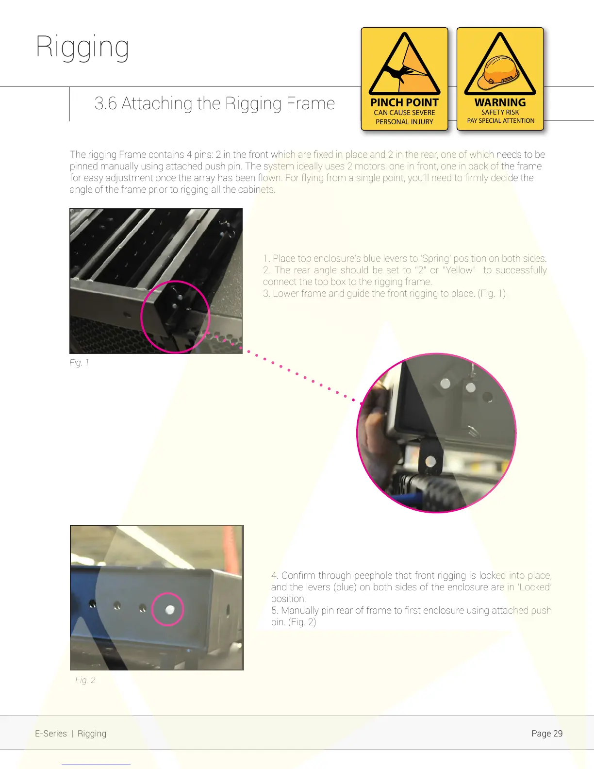
1. Place top enclosure’s blue levers to ‘Spring’ position on both sides.
2. The rear angle should be set to “2” or “Yellow” to successfully
connect the top box to the rigging frame.
3. Lower frame and guide the front rigging to place. (Fig. 1)
4. Conrm through peephole that front rigging is locked into place,
and the levers (blue) on both sides of the enclosure are in ‘Locked’
position.
5. Manually pin rear of frame to rst enclosure using attached push
pin. (Fig. 2)
Fig. 1
Fig. 2
The rigging Frame contains 4 pins: 2 in the front which are xed in place and 2 in the rear, one of which needs to be
pinned manually using attached push pin. The system ideally uses 2 motors: one in front, one in back of the frame
for easy adjustment once the array has been flown. For flying from a single point, you’ll need to rmly decide the
angle of the frame prior to rigging all the cabinets.
Rigging
E-Series | Rigging
PINCH POINT
CAN CAUSE SEVERE
PERSONAL INJURY
WARNING
SAFETY RISK
PAY SPECIAL ATTENTION