Page 37
3.11 Attaching Tops to Subs
E12 / E15 as an Underhang
Pictures shown are E12 and E218, the same principles apply to
the E15 and E219.
1. Set all E12 angles while still on the dolly.
2. Set blue levers on the top E12 box to ‘Spring’ mode.
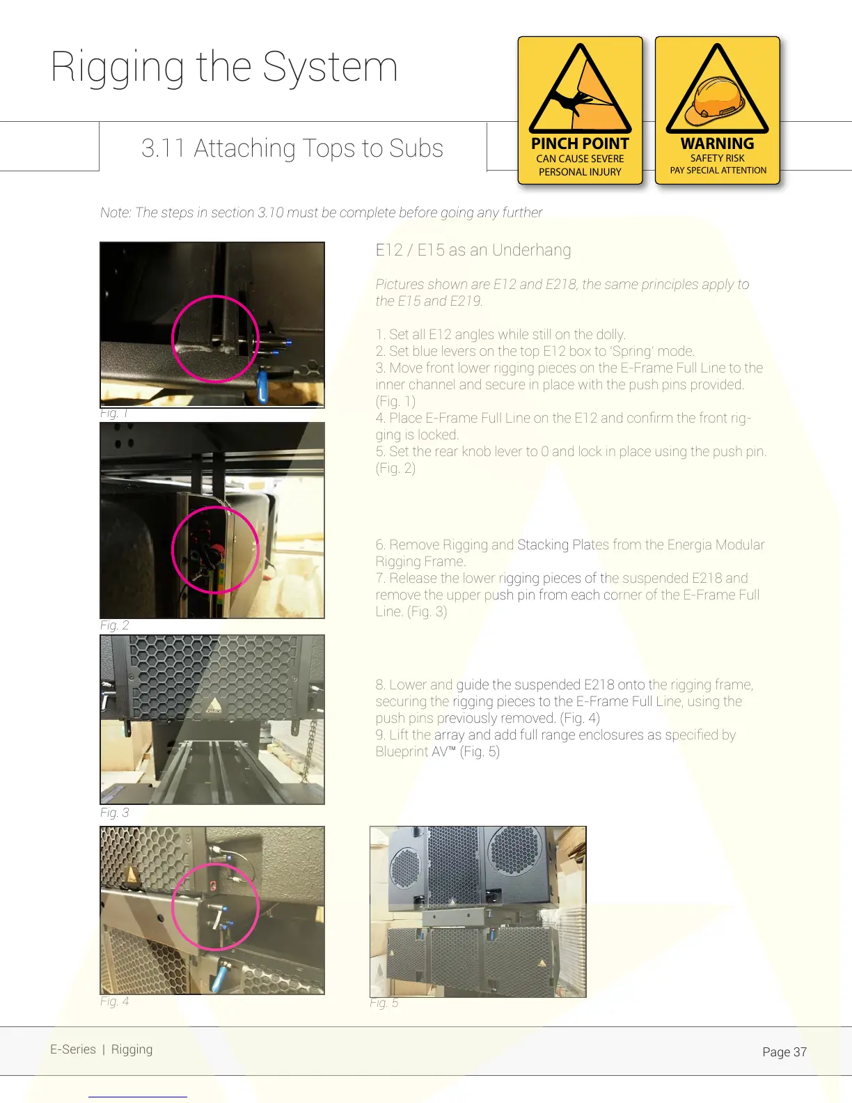
3. Move front lower rigging pieces on the E-Frame Full Line to the
inner channel and secure in place with the push pins provided.
(Fig. 1)
4. Place E-Frame Full Line on the E12 and conrm the front rig-
ging is locked.
5. Set the rear knob lever to 0 and lock in place using the push pin.
(Fig. 2)
Fig. 1
Fig. 2
Fig. 3
Fig. 4
Fig. 5
Rigging the System
E-Series | Rigging
PINCH POINT
CAN CAUSE SEVERE
PERSONAL INJURY
WARNING
SAFETY RISK
PAY SPECIAL ATTENTION
8. Lower and guide the suspended E218 onto the rigging frame,
securing the rigging pieces to the E-Frame Full Line, using the
push pins previously removed. (Fig. 4)
9. Lift the array and add full range enclosures as specied by
Blueprint AV™ (Fig. 5)
6. Remove Rigging and Stacking Plates from the Energia Modular
Rigging Frame.
7. Release the lower rigging pieces of the suspended E218 and
remove the upper push pin from each corner of the E-Frame Full
Line. (Fig. 3)
Note: The steps in section 3.10 must be complete before going any further