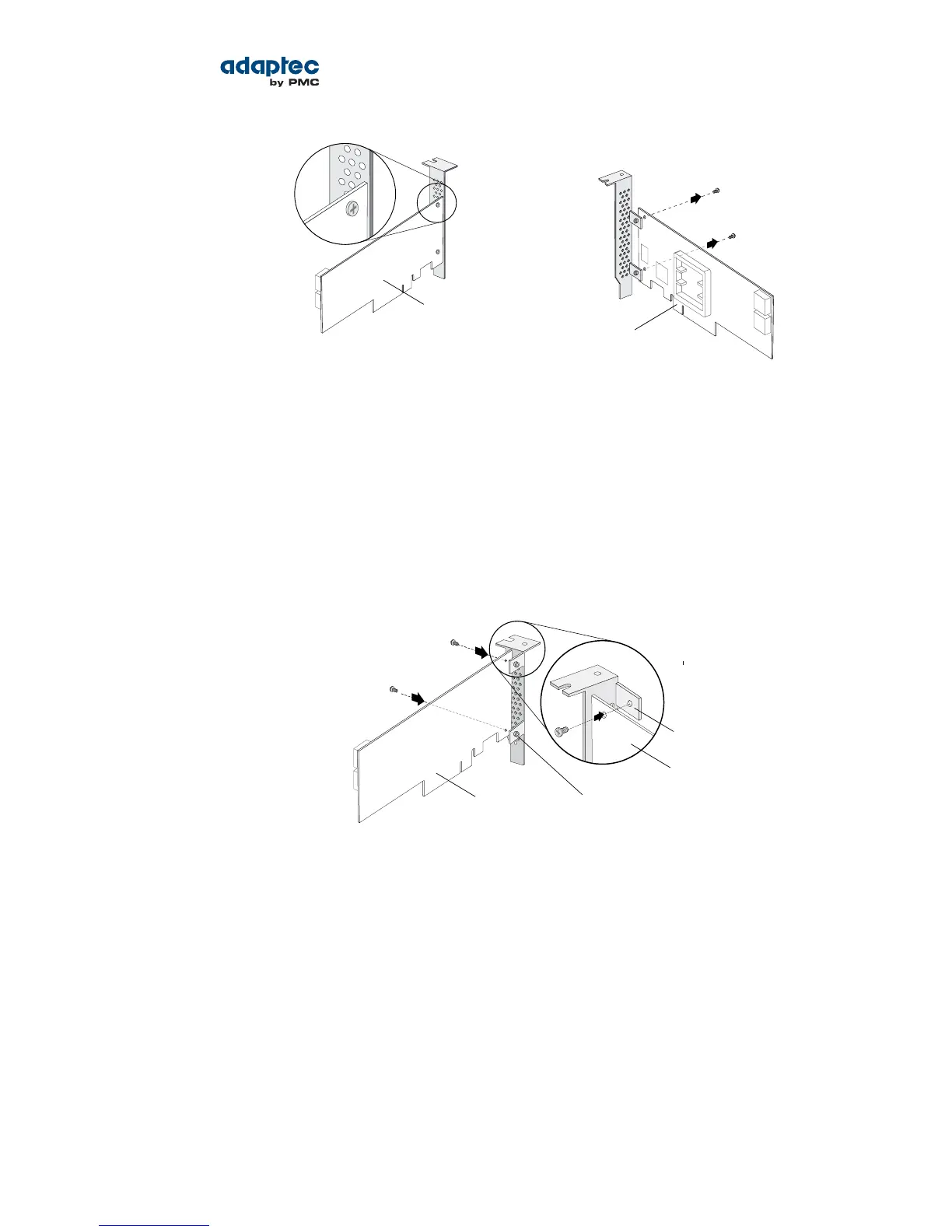
Remove mounting
screws with Phillips
screw driver
Front of board
Figure 2
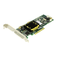
2. Attach the low-prole bracket to the controller board. The low-prole bracket is installed on the
back side of the controller, with the mounting screws inserted from the front of the controller, as
shown the Figure 3.
Insert the screws through the holes on the front of the controller, then fasten the screws to the
bracket with a Phillips screw driver.
Caution: The mount points on the low-prole bracket have a smooth or at side
and a raised side that looks like a spacer (see Figure 3). Be sure to install the bracket
with the at side against the controller PCB and the raised side facing away from
the PCB.
Raised side of bracket
Front of board
Flat side of bracket
Back of board
Caution: The torque on the mounting screws should be a maximum of 3.0-4.0
lbf-in to avoid deformation. Be sure that the controller is not bent after attaching
the low-prole bracket to the controller board.
Installation Options
When you install your Adaptec RAID controller, you can choose to create a bootable array and then
install your operating system and the controller driver on that array.
Alternatively, you can complete a standard installation, where the controller driver is installed on an
existing operating system.
Basic Installation Steps
This section describes the installation process. Follow the steps for the installation option you’ve chosen.
25Proprietary and Condential to PMC-Sierra, Inc.
Document No.: CDP-00277-01-A Rev. A, Issue:
Serial Attached SCSI RAID Controllers Installation and User's Guide