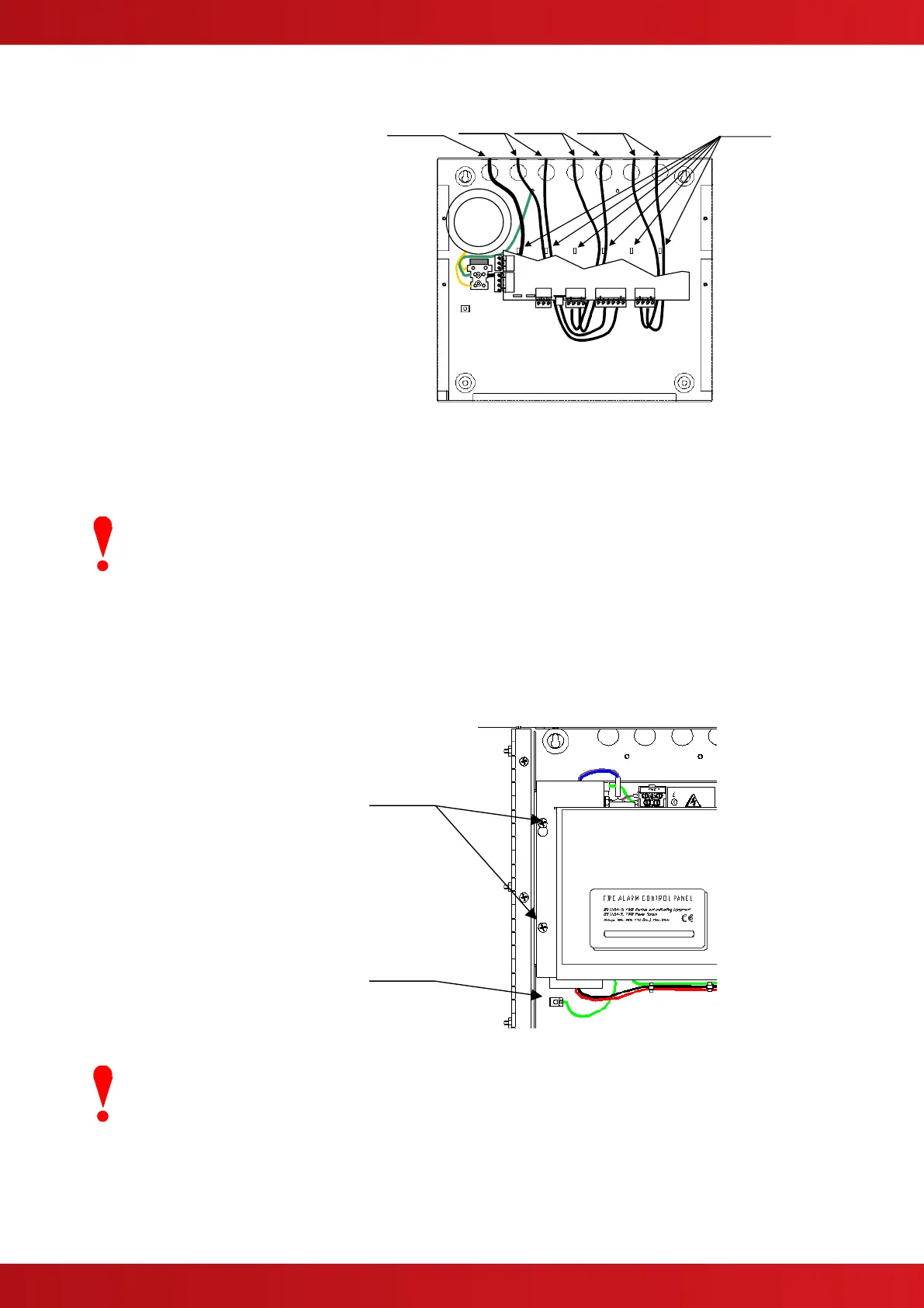
2.2.5 Recommended Cable Routing Arrangement
It is recommended that the routing
arrangement shown in the diagram
opposite be employed.
Segregate the low voltage wiring (Loop
Circuit, Sounder Circuits and AUX Supply)
from the AC Mains Wiring.
Segregate any wiring connected to the
relay contacts.
Eyelets are provided in the rear of the back
box to enable the cables to be securely
fastened using tie-wraps.
Refer to Appendix 2 – Recommended Fire
Rated Cables for further information on
cable types to be used.
Refer to specific sections on how to install
AC Mains input and loop, sounder, relay
and AUX outputs circuits.
Internal arrangement showing recommended routing of
cables.
2.3 Installing the Mx-4200 & 4400 Enclosures
The panel can weigh in excess of 20kg when the batteries are installed. Use the
appropriate fixing hardware necessary to secure the panel to the wall. Observe
recommended lifting practices to guard against spinal injury.
2.3.1 Opening the Enclosure Cover
The Mx-4200 & Mx-4400 are provided with a key-lock assembly for securing the hinged door to the back box.
Insert and turn the key to open the enclosure.
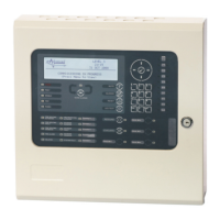
2.3.2 Removing the Chassis
It is recommended that the chassis be
removed before fitting the panel to the
wall. To remove the chassis:
Refer to the diagram opposite.
Disconnect the earth cable connecting
the chassis to the spade terminal on the
rear enclosure.
Remove the bottom two screws holding
the chassis to the back box. Keep these
items in a safe place for later re-use.
Loosen the top two screws holding the
chassis to the back box via the keyhole
slots. The chassis assembly can now be
removed.
Carefully remove the chassis from the
rear enclosure and place in a safe place
to prevent accidental damage.
Do not lift the chassis by holding onto any of the printed circuit cards. Hold the
chassis by the metal plate only.