2.6 Local Peripheral Modules
The Mx-4200, Mx-4400 and Mx-4800 panels provide provision for installation / use of local peripheral cards to
provide additional functions. The peripherals are connected via an isolated bus interface.
The panel supports the Mxp-032 General Routing Interface and up to sixteen Mxp-034 4-Way Programmable
Sounder Modules and up to sixteen Mxp-035 4-Way Programmable Relay Modules
.
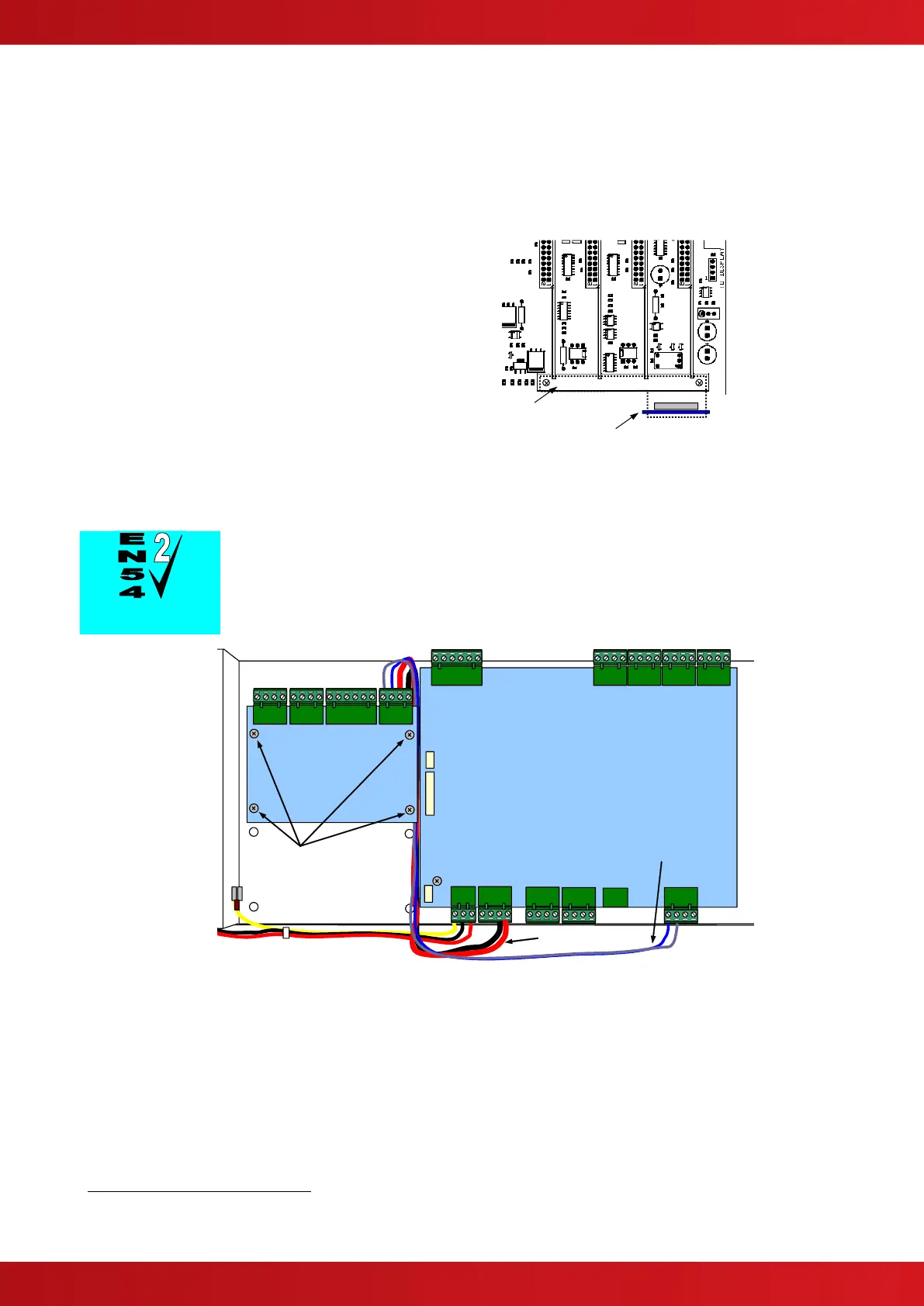
2.6.1 Peripheral Bus Interface Adaptor
To use the local peripheral bus Interface
requires the installation of an Adaptor Card –
Mxp-031.
Refer to the diagram opposite for location.
Secure the board in place (to prevent problems
due to vibration) using the clamping plate to
hold the card securely to the lower loop driver
location block.
A tab on the adaptor card fits into a slot in the
clamp.
Peripheral Interface Adaptor
Card
Note orientation
Clamp – use to hold Loop
Driver Cards and Peripheral
Interface Adaptor in place
Mounting Position for the Interface Adaptor
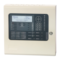
2.6.2 Routing Interface Card
Outputs to Routing Equipment – Clauses 7.9 and 8.9.
The Routing Interface Card (Mxp-032) provides monitored outputs for
connection to Fire Routing Equipment (Item E) and Fault Routing Equipment
(Item J) in accordance with EN54-2.
The card is
fitted to the
chassis using
4x M3 screws.
Refer to the
diagram
opposite.
Cables are
provided for
connection of a
local 24V DC
supply and
communications
connections.
Connect the DC
Supply from the
AUX output to
the connections
on TB4
observing
polarities.
Mounting Position for the Routing Interface Card
Connect the communications cable between TB3 on the Base Card and TB4 on the routing
interface so that 'A' is connected to 'A' and 'B' to 'B'.
For further information, refer to Document 680-081.
The Mxp-034 and Mxp-035 modules must be configured using the PC CONFIG TOOL. A maximum of 32 modules (of any type) can be
connected only. Refer to the installation guides provided with each module for further details.