3.3.8.1 Default Output Settings
On initial installation, or after clearing the configuration memory, all outputs are assigned to specific Output
Groups and will turn on immediately a single fire alarm occurs in any zone (any fault condition for the fault
relay). The default assignments are as follows:
Any fire in any zone – no delay
Any fire in any zone – no delay
Any fire in any zone – no delay
Any fire in any zone – no delay
Any fault in any zone – no delay
Any fire in any zone – no delay
On-board Open Collectors
7
Any fire in any zone – no delay
Any fault in any zone – no delay
Any fire in any zone – no delay
Any fire in any zone – no delay
Any fire in any zone – no delay
3.3.8.2 Cause
Each Output Group can be programmed to respond in a unique way to events from each individual zone. An
input event may be a fire alarm condition or it may be a fault, disablement or other condition. A combination of
criteria may also be applied to each zone.
The Cause field determines what type of input event (or a combination of input events) will generate an output
response for the selected input zone.
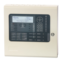
[Output Group 1] [ 3.9% Mem used]
ZONE CAUSE STYLE=Delay->MODE Wait
1 ANY FIRE 00 - On
2 ANY FIRE+ 00 - On
3 ANY FIRE 00 - On
4 ANY FIRE 00 - On
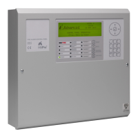
Press the ✔ button to change the setting and a pop-up window will appear showing the options available. For
example:
[FIRE ] [D/K FIRE] [ALARM][PRE-ALARM]
✔ - - -
[FAULT] [I/P DISABLE][TEST ][ CONTROL ]
- - - -
Press the buttons to highlight the required menu option and then press the ✔ to change its setting. An
input action type is enabled when a ‘✔’ is shown beneath the option. It is permitted to select multiple input types
in which case a combination of input events will result in an output action. If there is a combination of input
events, the CAUSE display above shows this extended programming by adding a ‘+’ to the text. For example,
Zone 2 above shows that the basic event is ANY FIRE + other criteria.
Press the ‘Esc’ button to return to the previous display.
Mx-4400 Only
This Output is used for routing if the non-monitored routing option is selected.
This Output is available on the optional Routing Interface Peripheral Card.