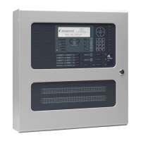
EasyManuals Logo

Advanced MxPro Series User Manual

Advanced MxPro Series
12 pages
To Next Page IconTo Next Page
To Previous Page IconTo Previous Page
Page #5 background imageLoading...
Page #5 background image
5
2 Installation
2.1 Enclosure
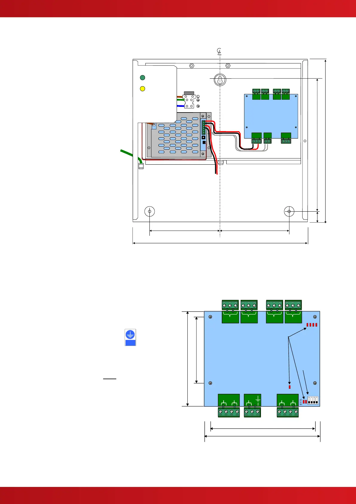
The enclosure dimensions,
fixing points and general
arrangement are shown in
FIGURE 1 opposite:
Space is provided in the
bottom of the enclosure for
2x 7AH batteries.
Enclosure cover is fixed to
the back box with 2x hex M4
screws.
Ensure that the earth lead
from the cover is securely
connected to the earth tab in
back box before refitting.
Cover is 345 (w) x 320 (h).
FIGURE1
2.2 PCB Mounting in Separate Enclosure
The printed circuit card shall be fitted to a metal
chassis or in a metal enclosure using the M3
spacers, nuts and screws supplied.
The chassis / enclosure must be connected
to protective earth.
Refer to the diagram opposite for dimensions and
fixing positions.
Fixing positions marked
*
must be securely fixed to
provide an earth connection for EMC purposes.
Brass spacers are provided for this purpose.
COM NO NC
B A
FLT
0V
24V
B A
[RELAY OUTPUTS]
[SERIAL BUS]
[POWER]
4-Way Relay Card
95.2
59.7
104.8
85.7
*
*
DIP
SWITCH
LED Status
Indicators
Relay
Heartbeat
Bus
TX RX
COM NO NC
COM NO NC
COM NO NC
FIGURE 2
135
135
340
24
315
255
F
U
SE
Battery
Leads
Earth
Lead to
Cover
Power
Fault
Must be
earthed

Questions and Answers:

Question and Answer IconNeed help?

Do you have a question about the Advanced MxPro Series and is the answer not in the manual?

Advanced MxPro Series Specifications

General IconGeneral
Product RangeAdvanced MxPro Series
Vibration Resistance10-55Hz, 1.5mm amplitude
Contact FormSPDT
Operating Voltage24V DC
Coil Voltage24V DC
Operate Time10ms
Release Time5ms
Insulation Resistance1000MΩ
Ambient Temperature+70°C
Dielectric Strength2500V AC

Related product manuals