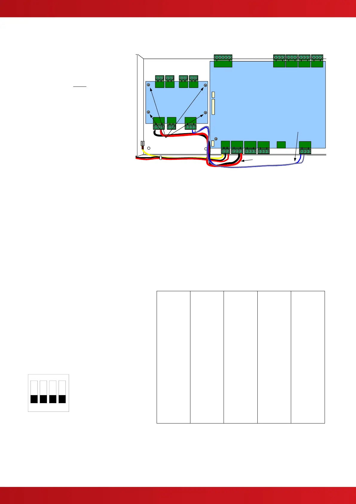
2.3 PCB Mounting in a 4200 / 4400 Panel
The card may be fitted to the chassis
using 4x M3 screws. Refer to Figure 3
opposite.
Screws marked
*
must be securely
fixed to provide an earth connection for
EMC purposes.
Where the unit is used for lightly
loaded outputs, the power may be
supplied by the AUX 24VDC panel
supply output.
In this case, check and ensure that the
power supply and battery standby can
support the application.
Wiring should be in accordance with subsequent sections of this manual.
Refer to FIGURE 3 above for the recommended routing of cables.
2.4 PCB Mounting in a 5000 Panel
There is provision on the 5000 chassis plate to mount one peripheral bus module (except 5100 small
enclosure). Refer to panel manual 680-165 for further information.
2.5 DIP Switch Configuration
Each 4-Way Relay Card must be given a unique
address.
The interfaces are added to the configuration
file in the PC CONFIG tool at Peripheral Bus
Address 66-81.
The DIP Switch on each unit must be set
accordingly to the corresponding address
defined. See table opposite.