2.6.3 DC Power and Serial Communications
A 24V DC power supply is required.
Connect the 24V DC supply feed input to the SUPPLY
+24V and 0V terminals on the interface card.
Use cables of sufficient size to ensure that the power
input voltage is maintained under all supply conditions
– refer to specifications section.
Note:
The DC power supply used MUST BE
designated a Safety Extra Low Voltage (SELV) supply.
For boxed versions, supplied complete with a power
supply, DC Power is pre-wired. Refer to details above
for the AC Power connections.
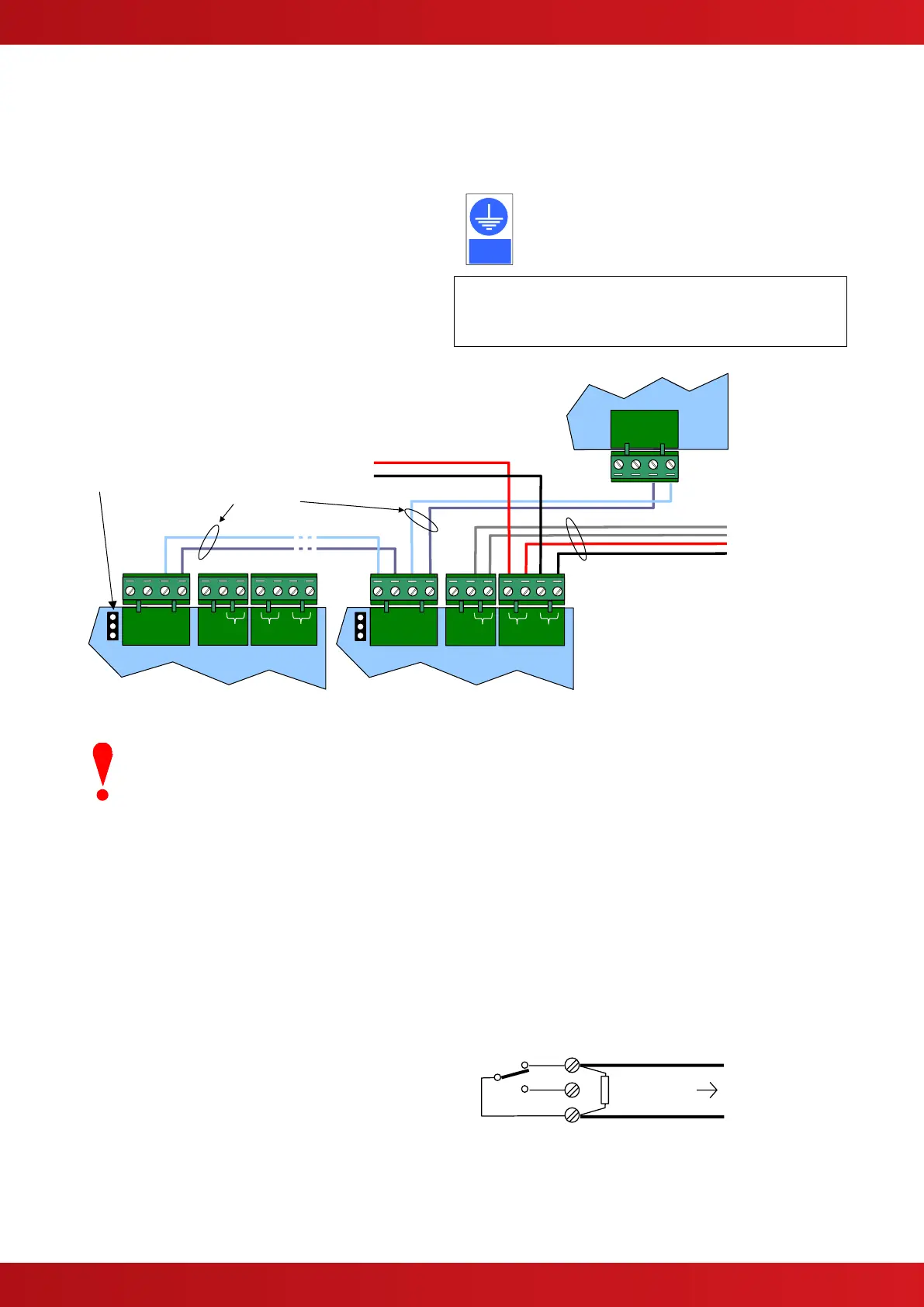
The enclosure in which the card is
mounted must be earthed and the card
fixing points defined in FIGURE 2 must
be connected to earth for EMC purposes.
OBSERVE POLARITY OF CONNECTIONS
Daisy chain the power to the
next unit if required.
24V DC POWER & Fault Output
from PSU
See below for specific installation
details of the Fault Input.
Daisy chain the communications line –
connect A-A and B-B
If the relay card is the last unit
on the signal line, set EOL
Termination jumper to connect
the internal 150Ω resistor.
Jumper = ON – with termination
Jumper = OFF – no termination
The serial communications is a 2-wire bus. Communications cable must be twisted-pair type. See
FIGURE 6 above for connections. Set the position of jumper 485 TERM to ‘ON’ to connect a 150Ω
EOL resistor on the last unit on the bus. Otherwise, leave this jumper in the ‘OFF’ position.
The interfaces and enclosures should be located not greater than 10M from the control panel (and
must be within the same room) with the wiring run in rigid metal conduit or using fire rated cables.
2.6.4 Power Supply Fault Input
The “FAULT INPUT” terminals are normally used to
monitor the contacts of the fault relay output from the
power supply.
A 10KΩ series resistor should be connected to the
relay terminals.
If more than one module is powered from the same
power supply, it is only necessary to connect the fault
output monitoring to one of the modules.
Should no fault relay be available, or if the monitoring
of an external fault signal is not required, these two
terminals should be shorted together with a 10KΩ
resistor across the terminals of the “FLT-INPUT”
terminal block.