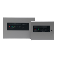
1.6 TECHNICAL SPECIFICATION
Electrical Specification Inputs & Outputs - TPCA01-X2/X4 Main PCB
0.5mm
2
to 2.5mm
2
solid or stranded wire
Power supply voltage control line
For temperature compensation control
28V
DC
supply input. Diode protected for
reversal and independent short circuit. Max
current 3 Amps
Max input current 3 amps. Input voltage
22V
DC
to 32V
DC
28V
DC
supply output for fire alarm accessory
relays etc. Max continuous use = 400mA
Fused @ 500mA. Fuse = 500mA resettable
fuse
Fire relay contact. Clean C/O. Max 3A @
30V
DC
Maintained fault relay contact. Clean C/O.
Max 3A @ 30V
DC
Switched -ve voltage outputs for relay
control.
Overload voltage protected to 52V
DC
.
Current limited 680R. Max load = 40mA
Switched -ve inputs, connect to 0v to trigger.
Max input voltage = 28V
DC
. Non latching,
max resistance 100R.
Protected via 10K Ohm impedance, 3V6
zener diode
28V
DC
polarity reversal monitored sounder
outputs to fire alarm devices. 4K7 Ohm 5%
0.25W EOL resistor.
Monitoring current limit 28mA, fused @
500mA. Typical max load 22 devices @
18mA each per circuit. Ensure 2.4A is not
exceeded.
Fire alarm zone circuits. Conventionally
wired detection circuit or Twin Wire
combined detection / sounder circuit. 4K7
Ohm 5% 0.25W EOL resistor
Monitoring current limit 50mA, fused @
500mA. Typical max load 22 alarm devices
@ 18mA each per circuit. Ensure 2.4A is not
exceeded.
Electrical Specification Inputs & Outputs - TPCA01-X2/X4 Main PCB
0.5mm
2
to 2.5mm
2
solid or stranded wire
Fire alarm zone circuits. Conventionally
wired detection circuit or Twin Wire
combined detection / sounder circuit. 4K7
Ohm 5% 0.25W EOL resistor
Monitoring current limit 50mA, fused @
500mA. Typical max load 22 alarm devices
@ 18mA each per circuit. Ensure 2.4A is not
exceeded.
Programmable Outputs OP A & OP B
Switched -ve voltage outputs for relay
control.
Overload voltage protected to 52V
DC
.
Current limited 680R. Max load = 40mA
Programmable relay Output
Fire relay contact. Clean C/O. Max 3A @
30V
DC
28V
DC
polarity reversal monitored sounder
outputs to fire alarm devices. 4K7 Ohm 5%
0.25W EOL resistor.
Monitoring current limit 28mA, fused @
500mA. Typical max load 22 devices @
18mA each per circuit. Ensure 2.4A is not
exceeded.
Electrical Specification Inputs & Outputs - TPCA05- comms PCB
Repeater Comms, fused @ 20mA
Programmable outputs 1 – 6
Switched -ve voltage outputs for relay
control.
Overload voltage protected to 52V
DC
.
Current limited 680R. Max load = 40mA
Steel IP30. Epoxy powder coated RAL7035
Fire resistant screened cable, minimum size 1mm
2
. Max cable length
1km (20 Ohm). FireBurn, FP200 or equivalent (max capacitance 1uF,
max inductance 1 millihenry).
Number of conventional/Twin Wire detection circuits
Conventional/Twin Wire detector compatibility
Apollo: S65, Orbis. / Hochiki CDX. / Nittan EV
www.acornfiresecurity.com
www.acornfiresecurity.com

 Loading...