EasyManua.ls Logo

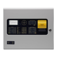
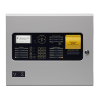
Advanced ExGo Ex-3001

Advanced ExGo Ex-3001
48 pages
To Next Page IconTo Next Page
Loading...
www.advancedco.com
Extinguishing Control Panel
Installation and Commissioning
The operation and functions described in this manual are available from Software Version Ex-3000-V2.05C onwards.

Table of Contents

Questions and Answers:

Advanced ExGo Ex-3001 Specifications

General IconGeneral
BrandAdvanced
ModelExGo Ex-3001
CategoryControl Panel
LanguageEnglish

Summary

ExGo Extinguishing Control Panel

Installation and Commissioning

Covers the installation, programming, and commissioning of the Extinguishing Control Panel.

Product Specifications

Part Number and Enclosure Details

Specifies the part number, enclosure type, dimensions, environmental class, and weight.

Power Supply and Battery Information

Details mains supply, power supply, battery capacity, and charging current.

Zone and Output Capacities

Lists the number of fire/flooding zones, actuator, sounder, and relay outputs.

Standards Compliance

Lists the EN standards the panel complies with.

Introduction and Standards

1.1 Standards

Lists compliance with EN standards for fire detection and extinguishing systems.

1.2 Cautions and Warnings

Important safety and installation precautions for personnel and equipment.

1.3 Description

Overview of the ExGo panel, its zones, and manual coverage.

EN54 Functions and Compliance

CIE Optional Functions

Lists optional functions compliant with EN54-2.

P.S.E Functions

Lists optional functions compliant with EN54-4.

EN54 Optional Features with Requirements

Details optional features beyond basic EN54-2.

Outputs to Fire Alarm Devices

Explains connection to fire alarm devices.

Delays to Outputs

Describes programmable output delay features.

Alarm Counter

Explains the function of counting alarm events.

Total Loss of Power

Configuration for annunciating total power loss.

Test Condition

Describes testing the installation on a per-zone basis.

EN12094 Functions and Features

EN12094-1 Compliance

Mandatory functions for automatic control and delay devices.

EN12094-3 Manual Trigger

Manual triggering device requirement.

Delay of Extinguishing Signal

Programmable delay for extinguishing signal.

Monitor Flow of Extinguishing Agent

Monitoring agent flow after release.

Emergency Hold Device

Provision for an emergency hold device.

Control of Flooding Time

Control over the duration of flooding time.

Manual Only Mode

Switching to manual-only operation mode.

Triggering Signals to System Equipment

Transmitting signals to system equipment.

Triggering Signals to External Equipment

Transmitting signals to external equipment.

Emergency Abort Device

Provision for an emergency abort device.

Activation of Alarm Devices with Different Signals

Activating alarms with varied signals.

Installation Approvals

Fire System Installations

Requirements for installation according to codes.

Wiring Regulations

Requirements for wiring according to codes.

Installation Procedures

2.1 Identification of Parts

Diagram and description of major panel components.

2.2 Installing the back box

Instructions and diagrams for mounting the enclosure.

2.3 Wiring Installation

Guidelines and procedures for connecting wiring to the panel.

Wiring Installation Details

2.3.1 AC Mains Wiring

How to safely connect the AC mains supply to the panel.

2.3.1.1 Cable Gland

Specifications and suggestions for cable glands and bushings.

2.3.2 Battery Wiring

Instructions for connecting 24V batteries to the PSE module.

2.3.3 24 VDC Power Supply Wiring

Wiring the main circuit card from the power supply.

2.3.4 PSE Configuration

Configuring the Power Supply Equipment module.

2.3.5 External Wiring

General notes on external wiring and EMC considerations.

External Wiring Procedures

2.3.5.1 Relay Outputs

Details on the four relay outputs and optional relay card.

2.3.5.2 RS485 Communications

Connecting to peripheral devices via RS485 bus.

2.3.5.3 AUX DC Supply Output

Specifications for auxiliary DC power outputs.

2.3.5.4 Detection Zone Inputs

Configuration and wiring of detection zone inputs.

2.3.5.4.3 Intrinsic Safe Arrangement

Using intrinsic safety detectors and barriers for zone circuits.

2.3.5.5 Sounder Monitored Output Circuits

Wiring and configuration of sounder output circuits.

2.3.5.5.1 Intrinsic Safe Arrangement

Using intrinsic safety sounders and barriers for sounder circuits.

2.3.5.5.2 EN54-13 Monitoring

Monitoring sounder circuits using Active EOL devices for EN54-13.

2.3.5.5.3 Sounder Circuit Lengths

Calculating voltage drop for sounder circuit lengths.

2.3.5.6 Input Circuits

Details on fixed and programmable input circuits.

2.3.5.7 Actuator Output Circuit

Driving igniting or solenoid actuators with the output circuit.

2.3.5.7.1 Igniting Actuators

Wiring and requirements for igniting actuators.

2.3.5.7.2 Solenoid Actuators

Wiring and requirements for solenoid actuators.

2.3.5.7.3 Solenoid Actuator Circuit Lengths

Calculating voltage drop for solenoid actuator circuits.

2.3.5.8 USB

Connecting a laptop or PC via USB for data transfer.

2.3.5.9 Recommended Cable Routing

Diagram showing recommended cable routing within the enclosure.

Panel Configuration and Setup

2.4 Key-Switch Installation

Procedures for installing key-switch assemblies.

2.5 Adjusting the LCD Contrast

How to adjust the contrast of the Liquid Crystal Display.

Loading Calculations

2.6.1 Panel Loading

Total panel load considerations and power supply limits.

2.6.2 Battery Standby Calculation

Calculating battery standby requirements.

Programming Overview

3.1 Introduction

Overview of panel configuration and programming.

3.1.1 Access Levels

Explains the four levels of access for panel operation.

3.1.2 Front Panel Controls and Indications

Description of controls and indicators on the front panel.

3.1.3 Enable Controls

How to enable panel controls using passwords.

3.1.4 Navigating through menus

Instructions for navigating the panel's menu system.

3.1.5 Numeric data entry

How to enter numeric data within the panel menus.

3.2 Recommended Programming Procedure

Recommended sequence for configuring panel options.

3.3 Level 3 Menu Functions

Lists and describes functions available at Level 3 access.

Menu Functions and Configuration

3.3.1 Detection Zones

Configuration of the three detection zone input circuits.

3.3.2 Alarms

Details on sounder outputs and their configuration.

3.3.2.1 Sounder Configuration

Detailed settings for configuring each alarm sounder output.

3.3.2.2 Pulse Pattern Configuration

Configuring different pulse patterns for alarm devices.

3.3.3 Extinguishing

Covers actuator output, cause & effect, and extract setup.

3.3.3.1 Output Set-Up

Configuring parameters for the actuator output.

3.3.3.2 Cause and Effects Programming

Defining release cause and effect rules.

3.3.3.3 Extract Set-Up

Configuration for the extract output signal.

3.3.3.4 Release Signal Termination (Test Function)

Special function to terminate active extinguishing control signals.

3.3.4 Inputs

Configuration of programmable inputs and their settings.

3.3.5 Outputs

List and configuration of programmable output options.

3.3.5.1 Switched AUX Output

Configuration of the switched AUX output.

3.3.6 Passwords

Menu for managing user and engineer passwords.

3.3.7 General Options

Configuration of various general panel options.

3.3.7.1 Daylight Saving Options

Configuration settings for daylight saving time.

3.3.8 Status Indicators

Configuration of remote status indicator panels.

3.3.9 Enable PC LINK

Enabling PC connection for data upload and download.

3.3.10 Exit

Procedure for exiting the commissioning/programming menu.

Service and Maintenance

4.1 Maintenance Schedule

Recommended schedule for daily, monthly, quarterly, and annual checks.

4.1.1 Daily Actions

User checks to perform daily for system operation.

4.1.2 Monthly Actions

User checks to perform monthly for system maintenance.

4.1.3 Quarterly Actions

Maintenance tasks for service contractors on a quarterly basis.

4.1.4 Annual Actions

Comprehensive annual maintenance checks and testing.

4.2 Replacement of Components

Information on replacing components like batteries and displays.

4.2.1 Batteries

Information on battery replacement, types, and installation.

4.2.2 Liquid Crystal Display

Guidance on replacing the LCD display.

Appendices

5.1 Appendix 1 - Forgotten Level 3 Password

Procedure to obtain a temporary permit number if password is lost.

5.2 Appendix 2 - Compatible Devices

List of compatible detectors with part numbers and zone capacity.

5.2.1 Detectors

List of compatible detectors with part numbers and zone capacity.

5.2.1 Detectors

Further list of compatible detectors with part numbers and zone capacity.

5.3 Appendix 3 - Recommended Cables

Recommended fire-rated and non-fire-rated cables.

5.3.1 Fire Rated Cables

Recommended fire-rated cables with core sizes and ratings.

5.3.2 Non-Fire rated cables

Recommended non-fire-rated cables for RSI/RS485.

5.4 Appendix 4 - Troubleshooting

Common symptoms and their potential causes and solutions.

Related product manuals